Screw for fixing resonant bar, cavity filter and communication equipment

A technology of cavity filter and resonant rod, which is applied in the direction of screws, mechanical equipment, waveguide devices, etc.

Active Publication Date: 2013-01-16
ANHUI TATFOOK M&E TECH
View PDF4 Cites 0 Cited by
  • Summary
  • Abstract
  • Description
  • Claims
  • Application Information

AI Technical Summary

Problems solved by technology

[0005] In order to solve the problems caused by the transition zone on the fixing screw of the resonating rod, the present invention provides a screw for fixing the resonating rod and a filter and communication equipment using the screw

Method used


Image

  • Screw for fixing resonant bar, cavity filter and communication equipment
  • Screw for fixing resonant bar, cavity filter and communication equipment
  • Screw for fixing resonant bar, cavity filter and communication equipment

Examples


Embodiment 1

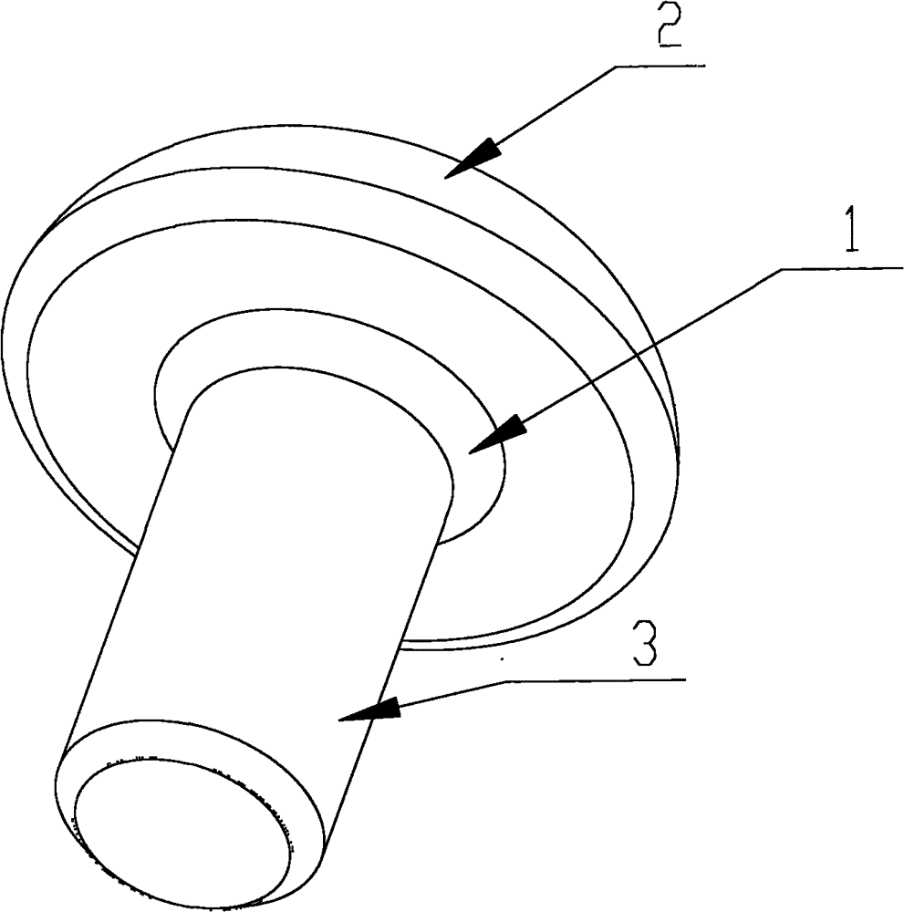
[0026] Embodiment one, as Figure 4 with Figure 5 As shown, a screw for fixing a resonant rod has a shank 23 with at least partial threads, one end of the shank is a screw head 21, and a transition zone 22 is between the screw head 21 and the shank 23 , there is an annular groove 24 around the transition zone 22 with the rod portion 23 as the center, the transition zone 22 is sunk in the groove 24, the depth of the groove is greater than the height of the transition zone, and the fixed resonance When the rod is connected, the top surface 25 of the groove exerts pressure on the bottom of the resonant rod to fix the resonant rod. The screw head 21 may be round, square or other shapes, the shape of the screw head is not enough to limit the present invention.

[0027] The end of the shank 23 of the screw in contact with the bottom surface of the screw head is a fixed end, and the end far away from the screw head is a free end. There are threads on the screw shank, and the dist...

Embodiment 2

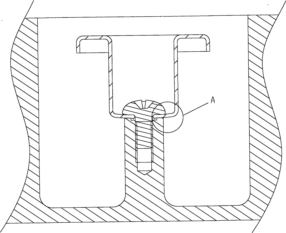
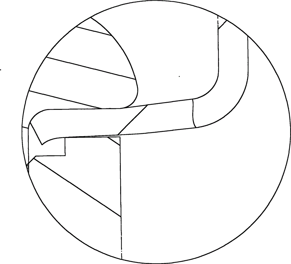
[0032] Embodiment 2. A cavity filter provided by this embodiment, such as Image 6 with Figure 7Shown are the sectional view and partial enlarged view of the cavity filter provided by this implementation, including a cavity 31, a resonant tube 32 and a screw 33, a support seat 34 is provided in the cavity, and a support seat 34 is provided on the bottom surface of the resonant tube 32. There is a through hole, and the screw passes through the through hole to fix the resonant tube 32 on the support seat 34 in the cavity 31. The screw 33 has a shank with at least a part of thread, and one end of the shank is a screw head There is a transition area between the screw head and the shank, and there is an annular groove around the transition area with the shank as the center, the transition area is sunk in the groove, and the groove depth is greater than the When fixing the resonant rod, the top of the groove exerts pressure on the bottom of the resonant rod to fix the resonant rod...


PUM


Abstract

The invention discloses a screw for fixing a resonant bar, a filter adopting the screw and communication equipment adopting the cavity filter; the screw is provided with a bar part which is at least locally provided with a thread; one end of the bar part is a screw head; a transition area is formed between the screw head and the bar part; a circular groove is arranged around the transition area with the bar part as the center; the transition area is arranged in the groove; the depth of the groove is more than the height of the transition area; and when the resonant bar is fixed, the top surface of the groove presses the bottom of the resonant bar, so that the resonant bar is fixed. The cavity filter adopts the screw, the transition area of the screw is arranged in the groove, so that the transition area does not press the bottom surface of the resonant bar, the resonant bar can be very well fixed under the condition that the screw has equal stress, and the phenomena that the resonant bar deforms and the performance of the filter is affected due to the transition area do not exist. The communication equipment adopts the cavity filter, so that the filtering performance can be very well realized.

Description

technical field [0001] The invention relates to a communication device, in particular to a cavity filter and a communication device using the cavity filter. Background technique [0002] As an important communication device, cavity filter plays an irreplaceable role in the field of radio transmission. [0003] A cavity filter usually includes a cavity and a resonance tube, the cavity is provided with multiple cavities, and each cavity accommodates a resonance tube. In order to ensure that the cavity filter can effectively filter out noise and interference signals, the connection between the resonant tube and the cavity in the cavity filter must be tightly structured. At present, there is a through hole at the bottom of the resonant tube in the cavity filter, and then the fixing screw The resonance tube is fixed on the supporting seat of the cavity through the through hole. Such as figure 1 As shown, the fixing screw is stamped by stamping equipment, including the screw he...

Claims


Application Information

Patent Timeline
Patent Type & Authority Patents(China)
IPC IPC(8): F16B35/00H01P1/207H01P1/20
Inventor 茹志云
Owner ANHUI TATFOOK M&E TECH
Why Eureka
Try Eureka