A high-precision instrumented indenter and a method for calculating the indentation depth of a diamond indenter
An instrumented press-in, high-precision technology, applied in the direction of instruments, scientific instruments, electric/magnetic depth measurement, etc., can solve the problem of inaccurate measurement of the tip of the indenter
Inactive Publication Date: 2011-12-21
ACADEMY OF ARMORED FORCES ENG PLA
View PDF5 Cites 33 Cited by
- Summary
- Abstract
- Description
- Claims
- Application Information
AI Technical Summary
Problems solved by technology
[0005] The purpose of the present invention is to provide a high-precision instrumented indenter and a calculation method for the depth of the diamond indenter indented into the sample, s
Method used
View moreImage
Smart ImageViewing Examples
Examples
 PUM
 Abstract
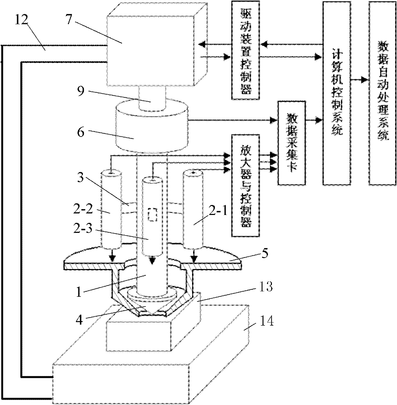
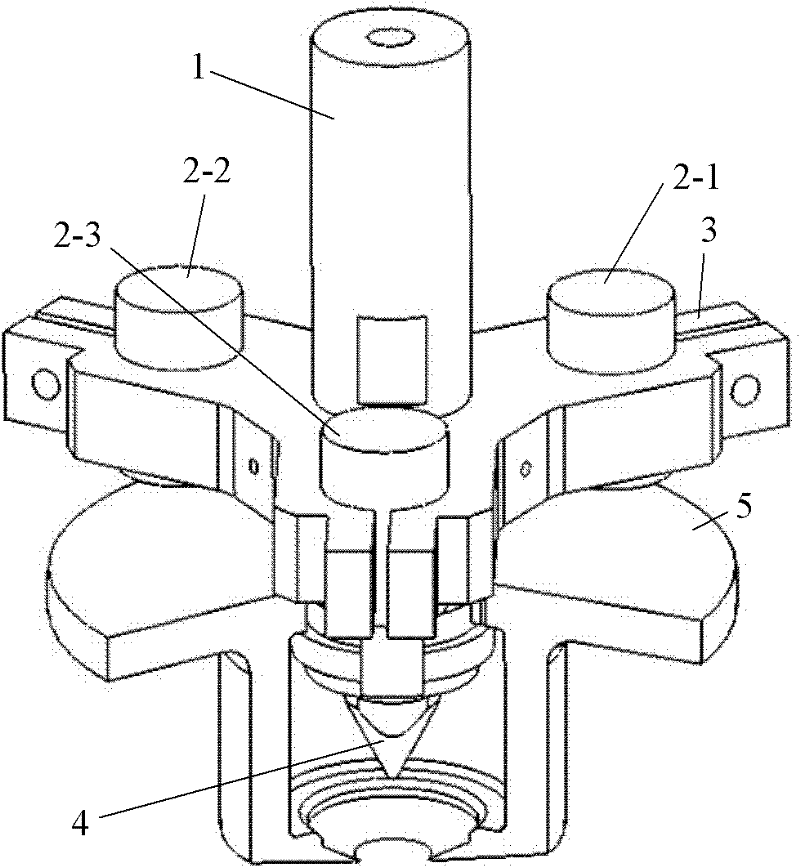
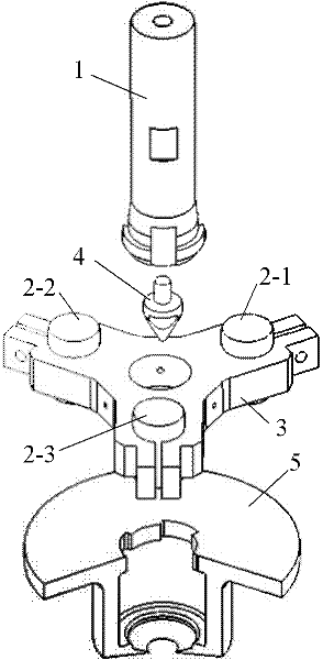
The invention discloses a design of an instrumented indenter. A driving and load testing system adopts a design that a voice-coil linear motor is connected in series with a load sensor and an indenting head subassembly; an indenting-in-sample depth testing system for a diamond indenting head adopts a design that three probe type capacitor displacement sensors are combined with a depth measuring follow-up disc; a computer control system is designed to have an open-loop working mode and a closed-loop working mode according to different test progresses, and can control the voice-coil motor, so as to control the diamond indenting head to carry out tests of indenting loading, load keeping, unloading and the like on the surface of a sample; and simultaneously, the relationship of an indenting load, an indenting depth and time can be obtained. By using the design, the influence on the measurement of an indenting-in-sample depth of the indenting head as the surface of the sample generates small-angle inclination with respect to a horizontal plane and the surface of the sample generates transitional displacement along a vertical direction due to a supporting factor or a clamping factor in a process that the sample is indented is eliminated; simultaneously, the influence of the flexibility of a frame on the measurement of the indenting-in-sample depth of the indenting head is also eliminated; and the precision of the indenting-in-sample depth of a testing indenting head is guaranteed.
Description
technical field [0001] The invention belongs to the technical field of testing mechanical properties of materials. In particular, it relates to the design of a high-precision instrumented indenter. Background technique [0002] With the rapid development of surface modification materials, thin film materials, MEMS (microelectronic micromechanical system) materials, composite materials, nanomaterials and other fields, the working reliability of surface, interface and microscale materials is challenged by harsh working conditions. It has drawn more and more people's attention and has become a research hotspot at home and abroad. However, due to the limitation of size, the traditional testing techniques and methods for mechanical properties of materials can no longer meet the needs of testing the mechanical properties of the above-mentioned materials, making the testing of the mechanical properties of material micro-regions become a key problem to be solved urgently. [0003]...
Claims
Login to View More Application Information
Patent Timeline
 IPC IPC(8): G01N3/42G01N3/06G01B7/26
Inventor 马德军宋仲康郭俊宏陈伟
Owner ACADEMY OF ARMORED FORCES ENG PLA
Features
- R&D
- Intellectual Property
- Life Sciences
- Materials
- Tech Scout
- Unparalleled Data Quality
- Higher Quality Content
- 60% Fewer Hallucinations
Learn More Browse by: Latest US Patents, China's latest patents, Technical Efficacy Thesaurus, Application Domain, Technology Topic, Popular Technical Reports.
© 2025 PatSnap. All rights reserved.Legal|Privacy policy|Modern Slavery Act Transparency Statement|Sitemap|About US| Contact US: help@patsnap.com


