
Method and device for state control of redundant power supply module

A technology of redundant power supply and state control, applied in circuit devices, emergency power supply arrangements, electrical components, etc., can solve the problems of reduced power supply service life, power waste, low power supply load rate, etc., to balance the number of shutdowns and reduce power consumption. , the effect of working time balance

Active Publication Date: 2011-12-21
UNITED INFORMATION TECH H K COMPANY +1
View PDF5 Cites 23 Cited by
  • Summary
  • Abstract
  • Description
  • Claims
  • Application Information

AI Technical Summary

Problems solved by technology

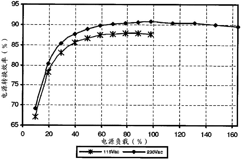
from figure 2 It can be seen from the figure that when the load rate is in the range of 40% to 90%, the power conversion efficiency is high, and when the load rate is lower than 20%, it is a light-load operation, and the power conversion efficiency is very low.
[0008] Therefore, regardless of the actual equipment load, if all the power supplies in the redundant power module work at the same time, the load rate of each power supply will be very low, the overall conversion efficiency of the power supply will be low, and a large amount of electric energy will be wasted, which does not meet the requirements of green energy saving.
And each power supply in the redundant power supply module is working all the time, and the service life of the power supply will also be reduced

Method used


Image

  • Method and device for state control of redundant power supply module
  • Method and device for state control of redundant power supply module
  • Method and device for state control of redundant power supply module

Examples


Embodiment Construction

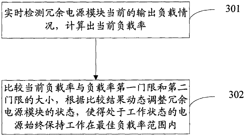
[0053] In the method for state control of redundant power supply modules proposed by the present invention, the first threshold of load rate and the second threshold of load rate are preset, wherein the first threshold is smaller than the second threshold; the basic flow of the method is as follows image 3 shown, including the following steps:

[0054] Step 301: Detect the current output load of the redundant power supply module in real time, and calculate the current load rate;

[0055] Step 302: Compare the current load rate with the first threshold and the second threshold of the load rate, and dynamically adjust the state of the redundant power supply module according to the comparison result, so that the power supply in the working state always works within the optimal load rate range. Specifically include: when the load rate of the device is less than the first threshold of the load rate, turn off one or more power supplies; when the load rate of the device is greater t...


PUM


Abstract

The invention provides a method for performing state control on a redundant power module. The redundant power module comprises at least two independent power supplies, and presets a first load rate threshold value and a second load rate threshold value, wherein the first threshold value is lower than the second threshold value. The method comprises the following steps of: A, detecting the currentoutput load conditions of the redundant power module in real time, and calculating a current load rate; and B, comparing the current load rate with the first load rate threshold value and the second load rate threshold value, dynamically regulating the state of the redundant power module according to comparison results, and specifically, switching one or more power supplies off when the load rateof equipment is lower than the first load rate threshold value, starting the one or more power supplies when the load rate of the equipment is higher than the second load rate threshold value and keeping the states of the power supplies invariable when the load rate of the equipment is between the first and second load rate threshold values. The invention also provides a device for performing thestate control on the redundant power module.

Description

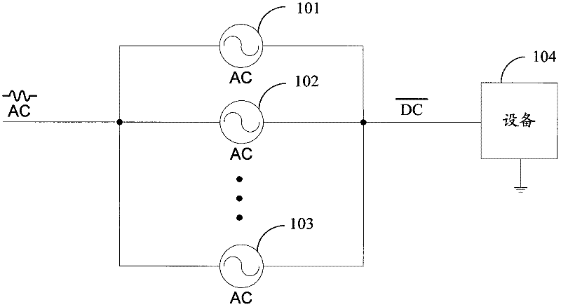
technical field [0001] The invention relates to the technical field of power supplies and batteries, in particular to a method and device for state control of redundant power supply modules. Background technique [0002] Many computer systems, including servers, storage, routers, and switches, require devices with high reliability and high availability. The power supply is the heart of the device, and multiple identical power supplies are usually connected in parallel to form a redundant power module to provide power to the device. [0003] The working mode of the redundant power supply module in the prior art is as follows: figure 1 shown. Multiple identical independent power sources (power source 101 , power source 102 , power source 103 , etc.) are connected in parallel to supply power to the device 104 . Under normal circumstances, each independent power supply in the redundant power supply module works together, and under the action of the control chip, load balance ...

Claims


Application Information

Patent Timeline
IPC IPC(8): H02J9/00
Inventor 唐斌
Owner UNITED INFORMATION TECH H K COMPANY
Learn More