A vehicle virtual composite display system

A technology for display systems and vehicles, which is applied to vehicle components, CCTV systems, components of TV systems, etc., and can solve problems such as limited driver behavior prompts and limited driver prompts.

Inactive Publication Date: 2011-12-21
毛湘伦
View PDF2 Cites 19 Cited by
  • Summary
  • Abstract
  • Description
  • Claims
  • Application Information

AI Technical Summary

Problems solved by technology

[0005] Therefore above-mentioned prior art only solves the problem of vehicle driver's blind spot, and promptly image only relates to the image near vehicle blind spot, and it does not involve other vehicle (obstacle) and relative position of this car, and this car is about to drive trajectory simulation, so it gives Driver behavior prompts are limited, especially when vehicles are overtaking, merging, or parking on the side of the road.

Method used


Image

  • A vehicle virtual composite display system
  • A vehicle virtual composite display system
  • A vehicle virtual composite display system

Examples


Embodiment Construction

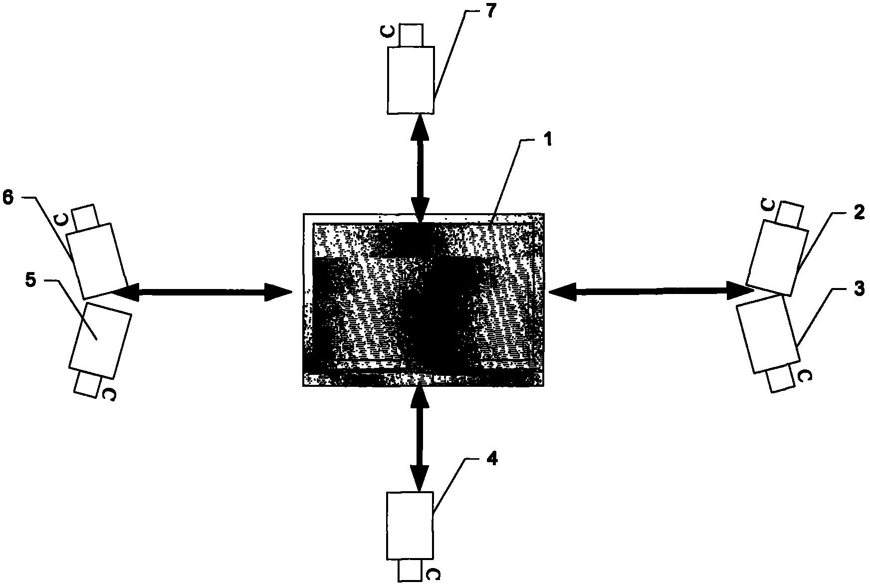
[0021] The present invention will be described in detail below in conjunction with the accompanying drawings. image 3 Shows the vehicle external image acquisition process of the present invention, the present invention assisted driving system includes a tablet computer 1, a vehicle right front camera 2, a vehicle right rear camera 3, a vehicle rear camera 4, a vehicle left rear camera 5, a vehicle left front camera 6, The vehicle front camera 7, the tablet computer 1 is placed on the central dashboard of the vehicle, the vehicle right front camera 2 and the vehicle right rear camera 3 are placed on the vehicle right rearview mirror, the vehicle left rear camera 5 and the vehicle left front camera 6 are placed On the rearview mirror on the right side of the vehicle, the vehicle front camera 7 is placed on the vehicle body in front of the front bumper of the vehicle, and the vehicle rear camera 4 is placed on the vehicle body behind the vehicle rear bumper. Above-mentioned camer...


PUM


Abstract

A vehicle virtual synthetic display system, which includes a tablet computer (1), cameras (2-7) around the vehicle (2-7), a driving computer (8), and a vehicle running state sensor (9-12), the tablet computer ( 1) The images transmitted by the cameras (2-7) are superimposed and synthesized to virtually generate a bird's-eye view panoramic image, the driving computer (8) acquires the vehicle data of the sensors (9-12) in good time, and the tablet computer (1) After invoking the vehicle data obtained by the driving computer (8) in good time, a vehicle motion trend trajectory image is generated, and the virtual bird's-eye view panoramic image is added to the bird's-eye view of the vehicle's own image, and the vehicle motion trend trajectory image is synthesized to generate a vehicle auxiliary judgment Bird's-eye panoramic imagery.

Description

technical field [0001] The invention relates to a virtual composite display system of vehicle exterior images, in particular to a virtual composite display system for vehicle auxiliary driving. Background technique [0002] Such as figure 1 As shown, Chinese patent application CN200910142345.X discloses a reversing image device with ranging function, which includes: a light source 10, a lens group 20 and a display 30. The light source 10 is installed at the rear of the car. The light source 10 can project light rays 11, and the light rays 11 generate patterns on the objects A and B to be tested; the lens group 20 is installed at the rear of the car, and the lens group 20 has a lens, a photosensitive component and a circuit board. Collect the image behind the car on the photosensitive component, and the circuit board calculates the distance between the object under test and the rear of the car according to the tightness of the pattern read by the photosensitive component; th...

Claims


Application Information

Patent Timeline
Patent Type & Authority Applications(China)
IPC IPC(8): H04N5/262H04N7/18B60R1/00
Inventor 毛湘伦
Owner 毛湘伦
Why Eureka
Try Eureka