Method, apparatus and system for assigning channels in a wireless mesh network
A wireless mesh network and channel technology, applied in wireless communication, network planning, network topology, etc., can solve the problems of mutual interference between network links and reducing WMN capacity.
- Summary
- Abstract
- Description
- Claims
- Application Information
AI Technical Summary
Problems solved by technology
Method used
Image

Examples
no. 1 example
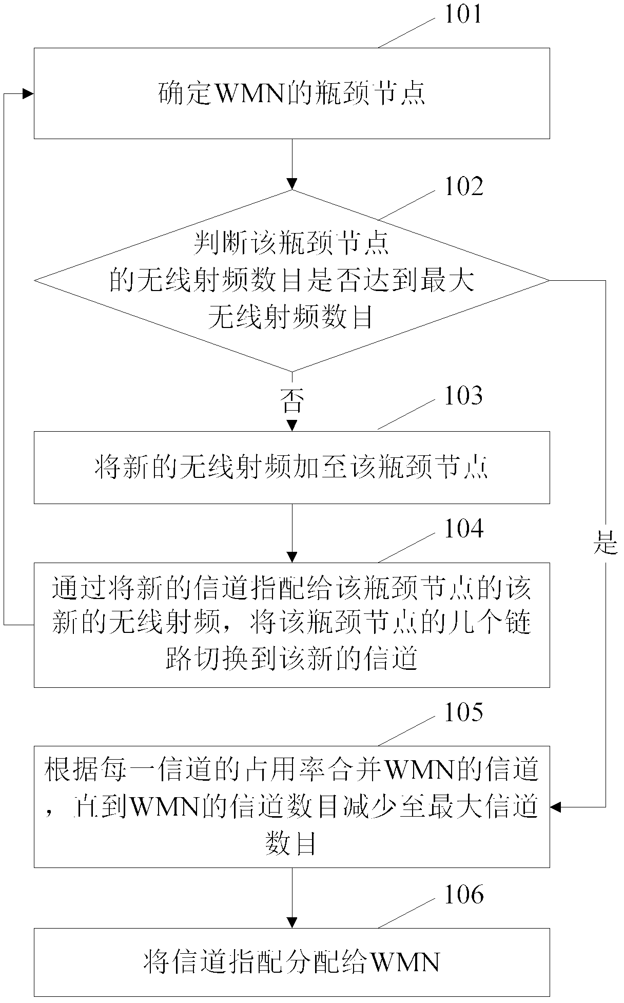
[0026] In the first embodiment of the present invention, a method for assigning channels in WMN is taken as an example to illustrate the technical solution. according to figure 1 As shown in the first embodiment of the present invention, a method for assigning channels in WMN includes the following steps:
[0027] In step 101, the bottleneck node of the WMN is determined.
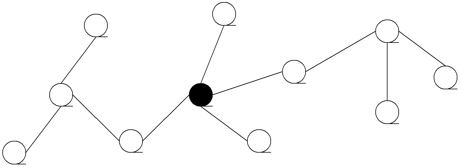
[0028] Using the state information of the WMN, such as the initial topology of the WMN, the flow rate of each link, and the rate of each link, there are many ways to determine the bottleneck node. For example, a node that is connected to a node having a wired link with an external network in a single hop may be determined as a bottleneck node. Another way to determine the bottleneck node is to use the occupancy rate of each node to evaluate the bottleneck node. The occupancy rate of a node means the proportion of time that is blocked by its neighboring node and transmitted to its neighboring node in the same c...
no. 2 example
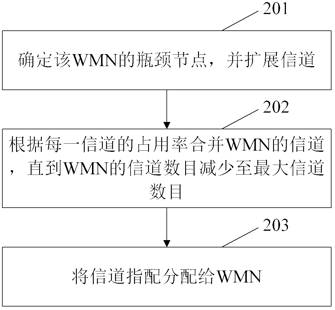
[0047] In the second embodiment of the present invention, a method for assigning channels in WMN is taken as an example to illustrate the technical solution. according to figure 2 As shown in the second embodiment of the present invention, the channel assignment method includes the following steps:
[0048] In step 201, the bottleneck node of the WMN is determined, and the channel is expanded.
[0049] The channel extension is the first important part of the channel assignment method. By ignoring the limit on the number of available orthogonal channels and considering only the maximum number of radio frequencies per node (given by overhead and / or execution limits), this channel extension expands the dual radio frequency WMN until no more wireless radios can be added. Radio frequency. In step 201, the channel extension may include several steps to add several new radio frequencies to different nodes.
[0050] Network splitting is the basic operation during MRMC WMN channel expansi...
no. 3 example
[0071] In the third embodiment of the present invention, a device for assigning channels in a WMN is taken as an example to illustrate the technical solution. according to Image 6 As shown in the third embodiment of the present invention, the channel assignment device includes the following modules:
[0072] The expansion module 61 is used to repeatedly determine the bottleneck node and expand the channel to create a channel assignment from the initial topology of the network;
[0073] The reduction module 62 is used to combine the channels assigned by the channels created by the extension module 61 according to the occupancy rate of each channel until the number of channels assigned by the channel is equal to the maximum number of channels;
[0074] The allocation module 63 is used to allocate the combined channel assignments combined by the reduction module 62 to the network.
[0075] The expansion module 61 may include the following units:
[0076] The storage unit 610 is used to s...
PUM
 Abstract
Description
Claims
Application Information