Method for automatically generating spraying layer arrangement plan of spray tower and device therefor

A technology for automatic generation and spraying of layers, applied in separation methods, chemical instruments and methods, dispersed particle separation, etc. The effect of easy operation and improved accuracy

Active Publication Date: 2010-07-28
BEIJING BOOTES ELECTRIC POWER SCI & TECH
View PDF0 Cites 2 Cited by
  • Summary
  • Abstract
  • Description
  • Claims
  • Application Information

AI Technical Summary

Problems solved by technology

This design method is not targeted, and the staff can only draw the graphics they need from the basic diagrams such as straight lines and circles according to their needs
Moreover, this method has a large workload, low efficiency, and is often error-prone and difficult to check.

Method used


Image

  • Method for automatically generating spraying layer arrangement plan of spray tower and device therefor
  • Method for automatically generating spraying layer arrangement plan of spray tower and device therefor
  • Method for automatically generating spraying layer arrangement plan of spray tower and device therefor

Examples


Embodiment Construction

[0049]There are usually multiple spray layers in the spray tower of the flue gas desulfurization system, and each spray layer has multiple nozzles arranged in one plane. Moreover, each spray layer has a pipeline for conveying circulating slurry, and these nozzles are arranged at intervals on the pipeline. When working, the pipeline transports the circulating slurry to each nozzle, and the nozzle sprays the slurry into the spray tower, so that the slurry contacts the flue gas in the spray tower, thereby washing the flue gas, so that the Pollutants (such as sulfur dioxide, etc.) in the flue gas are removed.

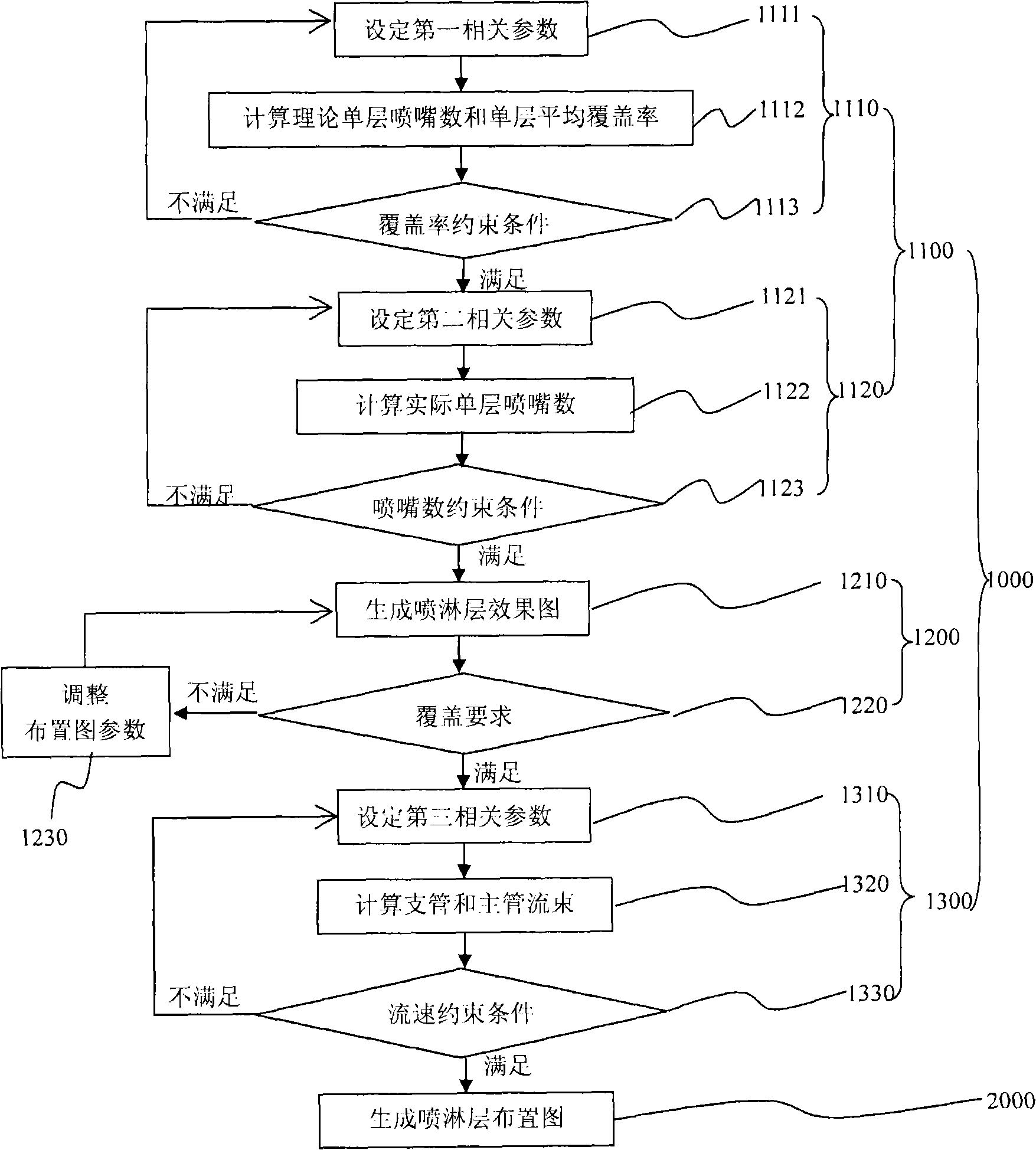
[0050] When designing the spray layer in the spray tower, it is usually necessary to design a spray layer layout diagram for each spray layer, such as Figure 8 The shown spray layer layout diagram generated according to an embodiment of the present invention is shown. Spray level layouts typically show the piping and nozzle layout, and optionally indicate various other l...


PUM


Abstract

The invention discloses a method for automatically generating a spraying layer arrangement plan of a spray tower and a device therefor. The spraying layer arrangement plan is automatically generated according to arrangement plan parameters by utilizing a specific program in a computer. In one embodiment of the invention, the arrangement plan parameters in a first part and a second part are determined based on a nozzle quantity constraint condition of constraining the single-layer nozzle quantity and a flow rate constraint condition of constraining the flow rate of circulating grout in a pipeline, and the arrangement plan parameters relevant to the nozzle arrangement are adjusted and / or determined according to the coverage requirements of the nozzle coverage state of the spraying layer. The method and the device improve the working efficiency of designers, and free the designers from the complicated work; meanwhile, the design accuracy is improved, and fault of the designers in the checking process is reduced.

Description

technical field [0001] The present invention relates to flue gas desulfurization technology, and more specifically, the present invention relates to a method and device for automatically generating a spray layer layout diagram of a spray tower. Background technique [0002] The spray tower is the core device of the flue gas desulfurization system. One or more spray layers are usually arranged in the spray tower, and multiple nozzles are distributed in each spray layer. The nozzles in the spray layer spray absorbent slurry to the inside of the spray tower, and the flue gas entering the spray tower contacts the slurry during the flow process, so that the slurry can absorb sulfur dioxide and / or other pollution in the flue gas thing. [0003] Spray layer layout is an important part of the flue gas desulfurization design, and the spray layer layout of the spray tower directly affects the spray effect and desulfurization efficiency. If the nozzle layout is unreasonable, it is e...

Claims


Application Information

Patent Timeline
Patent Type & Authority Applications(China)
IPC IPC(8): B01D53/78
Inventor 崔一尘王巧真吴树志白云峰顾利锋
Owner BEIJING BOOTES ELECTRIC POWER SCI & TECH
Why Eureka
Try Eureka