Optical disk device

An optical disc device, optical disc technology, applied in the directions of beam source, optical recording head, optical recording system, etc., can solve the problems of the target signal and the reproduced signal becoming larger, not necessarily jittering, and not sufficiently considering the reproduction and exchange, etc.

Inactive Publication Date: 2007-05-30
HITACHI CONSUMER ELECTRONICS CORP +1
View PDF5 Cites 1 Cited by
  • Summary
  • Abstract
  • Description
  • Claims
  • Application Information

AI Technical Summary

Problems solved by technology

On the other hand, its disadvantage is that since the target signal is generated as the coincidence of the impulse responses, the asymmetry of the target signal is zero except in special cases when the asymmetry of the signal recorded on the optical disc is not zero , the error between the target signal and the reproduced signal becomes larger
In JP-A-2003-6864, there is no mention of common FIR filter tap coefficients and frequency characteristics in the trial writing process.
In addition to this point, in the trial writing of the method of selecting the recording condition to meet the target signal of PRML, there is the following problem: the jitter may not be well maintained in the device other than the above-mentioned device, that is, insufficient consideration is given. regeneration swap
[0021] Issue 2: Consider not degrading the system performance of the regenerative system at the same time

Method used


Image

  • Optical disk device
  • Optical disk device
  • Optical disk device

Examples


no. 1 example

[0080] Component composition

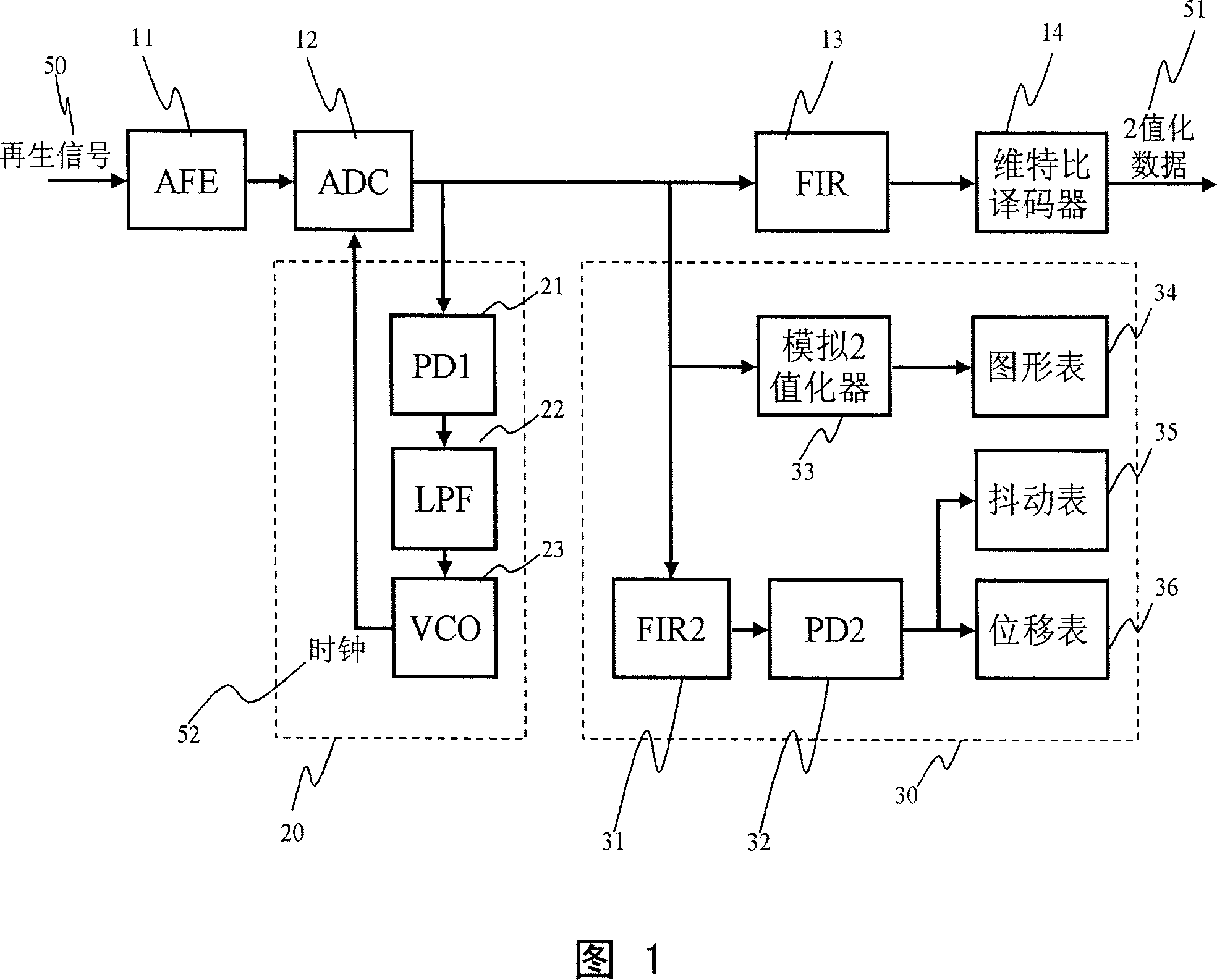
[0081] FIG. 9 shows an example of the configuration of a reproduced signal processing circuit suitable for an optical disc device of the present invention. The difference from the configuration shown in FIG. 1 is the following two points.

[0082] (1) Generalization of FIR filter

[0083] In the configuration of FIG. 1 , two FIR filters are provided: the FIR filter 13 for the Viterbi decoder 14 and the FIR filter 31 in the jitter measurement circuit 30 . When the limit length of the Viterbi decoder (referred to as the number of class bits) is an even number, it can be seen that the number of Taps of the FIR filter 13 is also an even number. In addition, because the test writing process and the recording / reproduction of normal data are not performed at the same time, the FIR filter 13 is a filter with variable tap coefficients. By switching the tap coefficients, the FIR filter 13 can also function as the FIR filter 31. Features. As the FIR fil...

Embodiment 2

[0087] Trial order

[0088] Hereinafter, before describing an embodiment of the trial writing procedure of the present invention using the drawings, a recording strategy for each DVD medium and the like will be described as preparations.

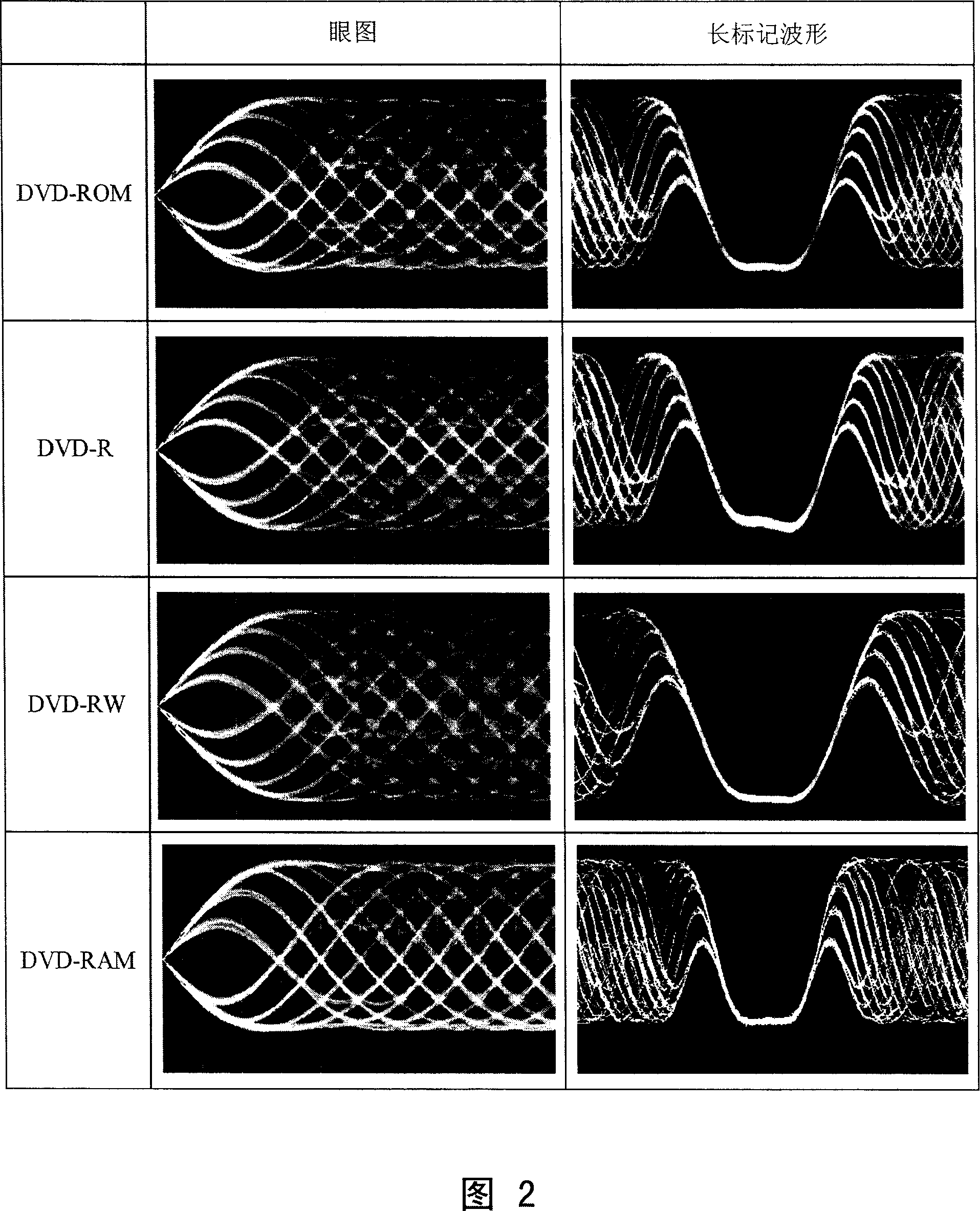
[0089] 10 and 11 schematically show recording strategies for DVD-R, DVD-RW, and DVD-RAM media. FIG. 10 shows standard speed recording conditions, and FIG. 11 shows high speed recording conditions. Each recording strategy is appropriately adopted according to the recording physics of the medium. The recording physics specific to each medium is beyond the scope of the present invention, so it will not be described in detail, but it is necessary to understand in order to rationalize the recording strategy.

[0090] In addition, in the following procedure, in addition to the measurement of the jitter realized in the present invention, the measurement of the asymmetry value, the β value, and the degree of modulation are also used together. The...

Embodiment 3

[0124] CD device

[0125] Fig. 25 shows an example of the configuration of an optical disc device according to the present invention. The optical disc medium 100 is rotated by the motor 160 . During reproduction, the laser power / pulse controller 120 controls the current flowing to the semiconductor laser 112 in the optical head 110 to generate laser light 114 so as to achieve the light intensity instructed by the CPU 140 . The laser beam 114 is condensed by the objective lens 111 to form a spot 101 on the optical disc medium 100 . The reflected light 115 from the light spot 101 is detected by the photodetector 113 through the objective lens 111 . The photodetector is composed of a plurality of photodetection elements. The reproduction signal processing circuit 130 reproduces the information recorded on the optical disc medium 100 using the signal detected by the optical head 110 . During recording, the laser power / pulse controller 120 converts predetermined recording data ...


PUM


Abstract

A write type optical disk device with the PRML mode allows accuracy in the trial writing to be improved accompanied with the high speed processing while assuring the readout compatibility. A readout signal that has been A / D converted at timing that interposes the edge has its phase compensated with the even numbered FIR filter. The level at the edge point and the absolute values thereof are accumulated respectively so as to provide a circuit for detecting the edge shift and jitter. Coping with the high speed processing, the edge shift of the readout signal is detected at the position where the edge shift is around zero, thus improving the accuracy in learning of trial writing.

Description

technical field [0001] The present invention relates to an optical disc recording device which forms recording marks having different physical properties from other parts on a recording medium and records information. Background technique [0002] Optical disk media such as DVD-RAM and DVD-RW using rewritable phase-change optical recording materials are widely used. Recently, a Blu-ray Disc with a larger capacity corresponding to high-definition broadcast video using a blue laser has also been commercialized. In the future, it is desired to realize an optical disc device capable of recording / reproducing DVD and Blu-ray Disc with a single drive. When recording information on these high-density optical discs, rationalization of the power and pulse conditions of recording laser light generally called "trial writing" is important. [0003] In the evaluation of the quality of a signal recorded on an optical disk, jitter in which the deviation between a data edge and a clock edg...

Claims


Application Information

Patent Timeline
Patent Type & Authority Applications(China)
IPC IPC(8): G11B20/10G11B7/00G11B7/0045G11B7/125
CPCG11B7/00456G11B7/005G11B7/0062G11B7/1267G11B20/10009G11B20/10037G11B20/10055G11B20/10296G11B20/10481G11B20/1816
Inventor 峰邑浩行
Owner HITACHI CONSUMER ELECTRONICS CORP
Why Eureka
Try Eureka