A jack for automatically pulling steel strands

A technology of steel strands and jacks, which is applied in the field of infrastructure engineering equipment, and can solve the problems of slow pulling of steel strands and high labor intensity of operators

Inactive Publication Date: 2011-12-28
SUZHOU NG FOUND ENG
View PDF6 Cites 4 Cited by
  • Summary
  • Abstract
  • Description
  • Claims
  • Application Information

AI Technical Summary

Problems solved by technology

The current method of pulling out the steel strand: use a conventional jack to pull out the steel strand. This type of jack only has a few components such as an oil cylinder, a piston, and a movable clamping part, and the movable clamping part loosens or clamps t

Method used


Image

  • A jack for automatically pulling steel strands
  • A jack for automatically pulling steel strands

Examples


Embodiment Construction

[0011] The present invention is described below in conjunction with accompanying drawing.

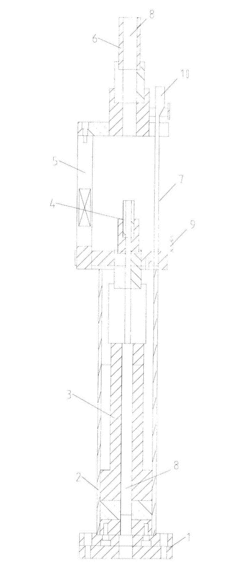
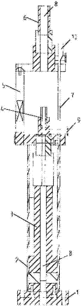
[0012] as attached figure 1 Shown is the jack of a kind of automatic drawing steel strand of the present invention,

[0013] Including base 1, oil cylinder 2, piston 3, movable clamping part 4, connecting rod 5, fixed clamping part 6, wire 7, through hole 8, movable electric control device 9, fixed electric control device 10; the oil cylinder 2 is fixed On the base 1, the piston 3 is arranged in the oil cylinder 2; the movable clamping part 4 is arranged on the upper part of the piston 3, and can move up and down following the piston 3; between the parts 6; the fixed clamping part 6 and the movable clamping part 4 are connected to the console by the electric wire 7 by the fixed electric control device 10 and the movable electric control device 9 respectively; the fixed electric control device 10 and the movable electric control device The device 9 can control the fixed clamping part 6...


PUM


Abstract

The invention relates to a jack for pulling steel strands, which includes a base, an oil cylinder, a piston, a fixed clamping part, a movable clamping part, a connecting rod, a guide part, electric wires, through holes, a fixed electric control device, a movable electric control device; the oil cylinder is fixed on the base, and the piston is set in the oil cylinder; the movable clamping part is set on the upper part of the piston, and can move up and down following the piston; the connecting rod is set between the oil cylinder and the fixed clamping part between; the fixed clamping part and the movable clamping part are respectively connected to the console by the fixed electric control device and the movable electric control device; the fixed electric control device and the movable electric control device can be fixedly clamped by the console control part and the movable clamping part to clamp or loosen the steel strand; the through hole passes through the base, the oil cylinder, the piston, the fixed clamping part and the movable clamping part to form a channel for accommodating the steel strand; The jack for pulling steel strands can continuously and automatically repeat the above two steps, and go round and round, so that the automatic drawing of steel strands can be realized.

Description

technical field [0001] The invention relates to a jack, in particular to a jack with a high degree of automation, which can reduce the manual workload and increase the drawing speed, and belongs to the technical field of infrastructure engineering equipment. Background technique [0002] With the advancement of urbanization, the construction of underground facilities such as underground parking lots, underground pedestrian passages, underground commercial streets, and underground railways requires foundation pit support. Although the use of internal support can well solve various problems generated during the construction of underground structures, its high cost, long construction period, and inconvenient construction of underground structures cannot meet the needs of urban development. [0003] In the prior art, in the Chinese patent with the patent number ZL201020022968.1, the inventor provides a hinge-type large-tonnage anchoring device; including hinge-type large-tonnage...

Claims


Application Information

Patent Timeline
IPC IPC(8): B66F3/24
Inventor 周建明施鸣升徐雷云
Owner SUZHOU NG FOUND ENG
Why Eureka
Try Eureka