
Magnetic conductive bath specifically for electroplating of insertion-type light-emitting diode (LED) support

A technology of LED bracket and in-line technology, applied in the direction of plating tank, etc., can solve the problems of easy oxidation conductive contact, peeling, large consumption of copper sheet, etc., and achieve the effect of enhancing the conductive effect

Active Publication Date: 2014-11-05
无锡鼎亚电子材料有限公司
View PDF6 Cites 0 Cited by
  • Summary
  • Abstract
  • Description
  • Claims
  • Application Information

AI Technical Summary

Problems solved by technology

The material is mainly made of copper, which is easily oxidized and causes poor conductive contact. The conductive wheel is replaced too frequently, and needs to be replaced or re-washed on average every week;
[0005] 2. Copper sheet friction conduction: First, the copper sheet is worn out due to the thinner conductive process. After the copper sheet is worn through, the conductive product has peeling and other defects. At the same time, the copper sheet consumes a lot and needs to be replaced every day on average.

Method used


Image

  • Magnetic conductive bath specifically for electroplating of insertion-type light-emitting diode (LED) support
  • Magnetic conductive bath specifically for electroplating of insertion-type light-emitting diode (LED) support

Examples


Embodiment Construction

[0017] In order to make the technical means, creative features, goals and effects achieved by the present invention easy to understand, the present invention will be further described below in conjunction with specific illustrations.

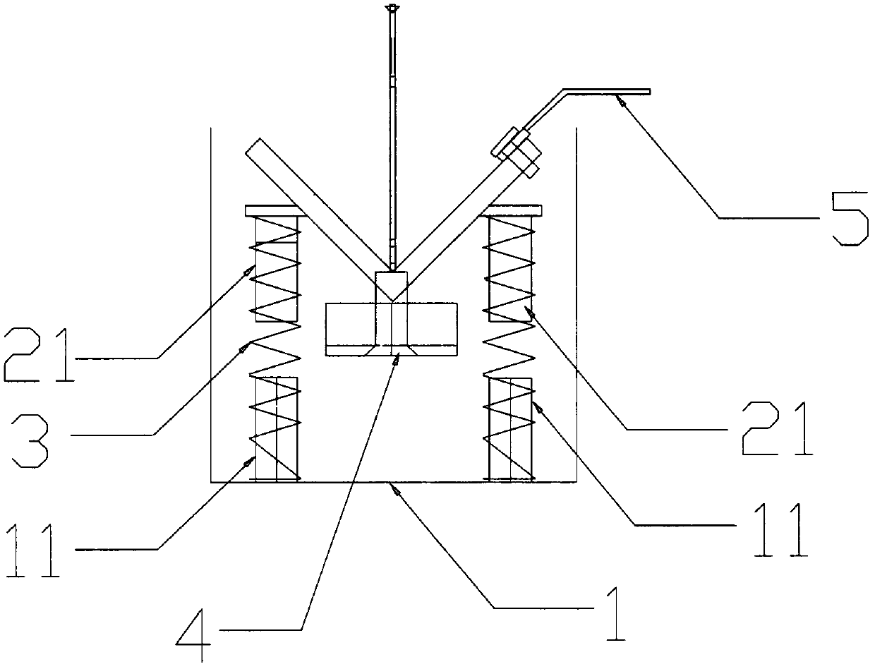
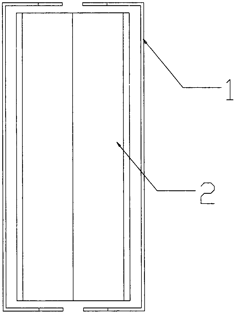
[0018] Such as figure 1 and figure 2 As shown, the electroplating special-purpose magnet conduction groove of in-line LED bracket of the present invention, it comprises rectangular stainless steel conduction seat 1, " V ​​" shape groove 2, spring 3 and permanent magnet 4; The inner bottom of described rectangular stainless steel conduction seat 1 is provided with There are plural pairs (usually two or more pairs are provided according to actual needs) of lower fixing columns 11 symmetrically distributed. The lower fixing column 11 corresponds to the upper fixing column 21 arranged below the "V"-shaped groove 2, and the "V"-shaped groove 2 and the rectangular stainless steel conductive seat 1 are connected by the outer spring 3 between each pai...


PUM


Abstract

The invention discloses a magnetic conductive bath specifically for electroplating of an insertion-type light-emitting diode (LED) support. The magnetic conductive bath comprises a rectangular stainless steel conductive base, a V-shaped groove and a permanent magnet. Plural pairs of lower fixing pillars distributed symmetrically are arranged at the bottom of the rectangular stainless steel conductive base. The lower fixing pillars correspond to upper fixing pillars arranged below the V-shaped groove. Each one of the upper fixing pillars and the lower fixing pillar corresponding to the one are connected by an outer sleeve spring, so that the V-shaped groove and the rectangular stainless steel conductive base are connected together and the V-shaped groove is suspended in mid-air. The permanent magnet is arranged below the V-shaped groove. One side of the V-shaped groove is fixed with an external conductive connecting line by a screw. The magnetic conductive bath can prolong service lives of conductive members and avoid a phenomenon of interruption of power supply simultaneously.

Description

Technical field: [0001] The invention relates to a conductive device, in particular to a magnet conductive slot specially used for in-line LED bracket electroplating. Background technique: [0002] At present, for the continuous electroplating of in-line LED brackets, the existing conductive technologies are mainly: 1. Cup-shaped conductive wheels; 2. Copper sheet friction conduction; [0003] The disadvantages of the above two conduction methods are: [0004] 1. Cup-shaped conductive wheel: During the electroplating process, the cup-shaped conductive wheel will cause the copper wheel and bushing to wear out due to long-term rotation, which will eventually cause the conductive wheel to not rotate, scratching the surface of the product and deforming the bracket. The material is mainly made of copper, which is easily oxidized and causes poor conductive contact. The conductive wheel is replaced too frequently, and needs to be replaced or re-washed on average every week; [00...

Claims


Application Information

Patent Timeline
Patent Type & Authority Patents(China)
IPC IPC(8): C25D17/02
Inventor 赵伟华黎阳通
Owner 无锡鼎亚电子材料有限公司
Learn More