Vibration-proof storage box for electronic device, the electronic device, and electronic equipment equipped with the electronic device
A technology for electronic devices and storage boxes, which is applied in the directions of poor vibration/sound insulation/absorption, record carrier structural parts, instruments, etc., can solve the problem of increased noise in storage devices, etc. Effect
- Summary
- Abstract
- Description
- Claims
- Application Information
AI Technical Summary
Problems solved by technology
Method used
Image
Examples
Embodiment approach 1
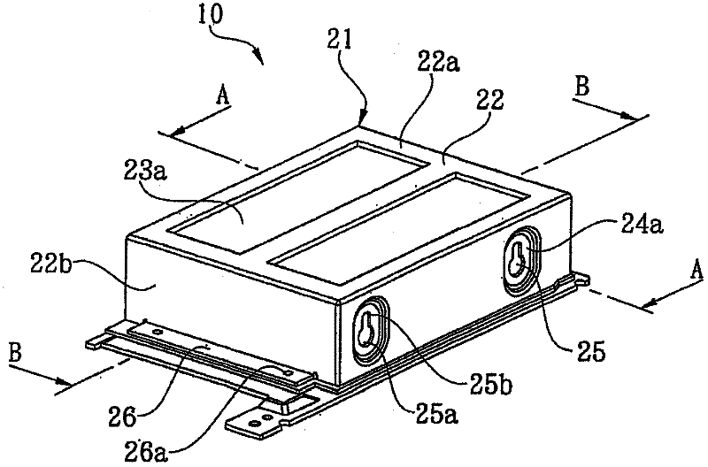
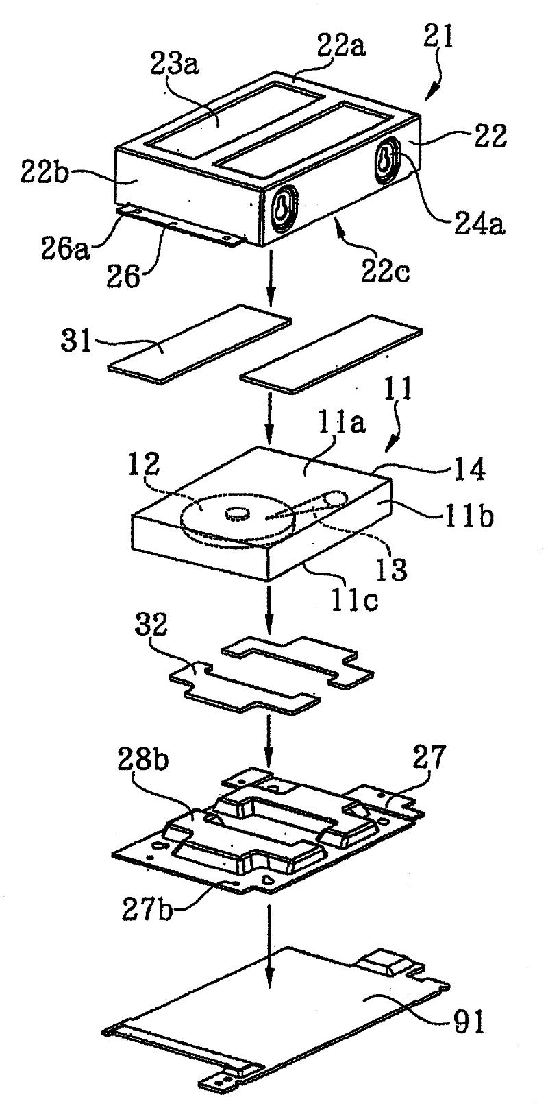
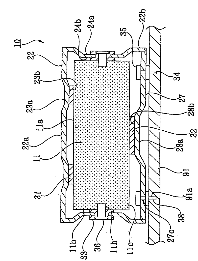
[0048] figure 1 It is a perspective view showing the appearance of the electronic device as the first embodiment of the present invention. figure 2 yes means figure 1 An exploded perspective view of the composition of the electronic device shown. image 3 yes means figure 1 The structure of the anti-vibration storage box of the electronic device shown along figure 1 A cross-sectional view of line A-A in. Figure 4 yes means figure 1 The structure of the anti-vibration storage box of the electronic device shown along figure 1 The cross-sectional view of the B-B line in. Figure 5 Yes means fixed figure 1 An enlarged vertical cross-sectional view of the main part of the vibration-proof storage box shown. Image 6 yes means Figure 5 The parts shown in the different parts, fixed figure 1 An enlarged vertical cross-sectional view of the main part of the vibration-proof storage box shown. Figure 7 It is a table showing the experimental results of the effects ob...
Embodiment 1
[0063] As Example 1, a shielded storage device 10 was manufactured by forming a vibration-proof storage case 21 for housing a hard disk drive as the storage main body 11 in the following dimensions and shapes. Figure 7 The result of measuring the noise when the shielded storage device 10 is assembled and mounted in different types of personal computers is shown.
[0064] As the vibration-proof storage box 21, a steel plate with a thickness of 1.6 mm was processed to manufacture the vibration-proof cover 22 and the vibration-proof plate 27, and the vibration-proof storage box 21 was formed into a box shape with a length of 220 mm, a width of 140 mm, and a height of 50 mm. On the upper surface portion 22a of the anti-vibration cover 22, a stepped convex portion 23b that is a step of 1.5mm is formed by drawing processing, and on the side surface portion 22b, a stepped convex portion 24b that is a step of 1.5mm is formed by drawing processing . Also on the anti-vibration plate 27,...
Embodiment approach 2
[0068] Figure 8 It shows the structure of the anti-vibration storage case of the electronic device which is the second embodiment of the present invention figure 1 The sectional view corresponding to the A-A line in . Figure 9 yes means Figure 8 The structure of the vibration-proof storage box for the electronic device shown in figure 1 The cross-sectional view corresponding to the B-B line in . The second embodiment has basically the same configuration as the above-mentioned first embodiment, so the same symbols are assigned to these same structures, and the characteristic parts will be described (the same applies to other embodiments described below).
[0069] Such as Figure 8 and Figure 9 As shown, in the storage device 40, instead of one of the vibration-damping members 31 attached to the stepped convex portion 23b of the vibration-proof cover 22 of the vibration-proof storage box 21 that accommodates the storage main body 11, a heat-conducting member 41 is pas...
PUM
 Abstract
Description
Claims
Application Information
 - R&D
- Intellectual Property
- Life Sciences
- Materials
- Tech Scout
- Unparalleled Data Quality
- Higher Quality Content
- 60% Fewer Hallucinations
Browse by: Latest US Patents, China's latest patents, Technical Efficacy Thesaurus, Application Domain, Technology Topic, Popular Technical Reports.
© 2025 PatSnap. All rights reserved.Legal|Privacy policy|Modern Slavery Act Transparency Statement|Sitemap|About US| Contact US: help@patsnap.com


