Blowing valve interlock control device

A technology of chain control and air valve, applied in the direction of valve device, valve operation/release device, valve details, etc., can solve the problems of cumbersome operation, high cost, complex structure, etc., achieve convenient use, simple structure, and improve production efficiency Effect

Inactive Publication Date: 2012-01-04
KARL MAYER CHINA
View PDF5 Cites 2 Cited by
  • Summary
  • Abstract
  • Description
  • Claims
  • Application Information

AI Technical Summary

Problems solved by technology

[0003] In order to overcome the shortcomings of the existing solenoid valve PLC independent control structure complex, cumbersome operation, and high cost, the present invention provides a blowing valve chain control device

Method used


Image

  • Blowing valve interlock control device
  • Blowing valve interlock control device

Examples


Embodiment

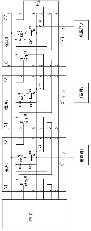
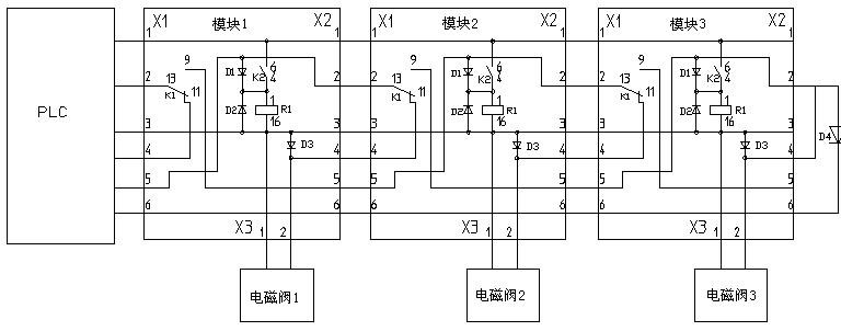
[0013] Embodiment: A blowing valve chain control device, including PLC, module group, relay module, solenoid valve and terminal plug, each relay module is connected to a solenoid valve, and the module group is formed by at least two relay modules connected in series, The PLC is connected to the head of the module group, and the terminal plug is connected to the tail of the module group to form a chain control circuit.

[0014] PLC inputs 24V signals to input port 1 and input port 5 of module 1 respectively, coil L in module 1 is energized, contacts 13 and 9 are connected, contacts 4 and 6 are connected, and self-protection; the other one is connected to the solenoid valve 1. Solenoid valve 1 is energized and opened.

[0015] Disconnect the 24V signal of the input port 5 of module 1, the solenoid valve 1 is de-energized and closed, input the 24V signal to the input port 2 of the module 1, pass through the 13 and 9 contacts of the module 1, come out from the output port 5 of the...


PUM


Abstract

The invention relates to the technical field of textile machinery, in particular to a blowing valve interlock control device, which comprises a programmable logic controller (PLC), a module assembly, relay modules, electromagnetic valves and a terminal plug, wherein each relay module is connected with an electromagnetic valve; the module assembly is formed by connecting at least two relay modules in series; the PLC is connected with the head of the module assembly; and the terminal plug is connected with the tail of the module assembly. In the blowing valve interlock control device, the relay modules are connected in series to form the module assembly so as to form an interlock control circuit; only one group of output ports of the PLC are used to output preset pulse signals, the required functions can be realized, and all electromagnetic valves are controlled to be opened or closed; and the blowing valve interlock control device is simple in structure and convenient to use, the cost is reduced and the production efficiency is greatly improved.

Description

technical field [0001] The invention relates to the technical field of textile machinery, in particular to an interlock control device for blowing valves. Background technique [0002] Each yarn on the GV creel must pass through a yarn clamping device, and a photoelectric sensor is installed on the yarn clamping device to detect whether the passing yarn is broken. Due to the poor environment in the warping workshop and a lot of dust and lint, a long time will not only affect the sensitivity of the photoelectric sensor, but also affect the yarn clamping effect of the clamping device, so the creel is equipped with a blowing and dust removal device for the yarn clamping device. The opening and closing of the blowing device is controlled by a two-position two-way solenoid valve. The more the number of ends of the creel, the more solenoid valves are used. The opening and closing of all solenoid valves are not carried out at the same time, but in a sequential cycle. To achieve s...

Claims


Application Information

Patent Timeline
Patent Type & Authority Applications(China)
IPC IPC(8): F16K31/06
Inventor 陈祝俊
Owner KARL MAYER CHINA
Why Eureka
Try Eureka