Frictional joint
A friction hinge and articulation technology, applied in door/window fittings, wing sash fasteners, building fasteners, etc., can solve the problems of inaccurate positioning and locking of friction hinges
- Summary
- Abstract
- Description
- Claims
- Application Information
AI Technical Summary
Problems solved by technology
Method used
Image

Examples
Embodiment 1
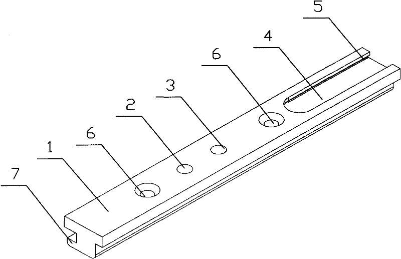
[0034] The three-dimensional structure diagram of the friction hinge frame fixing plate is as follows figure 1 As shown, among them: 1 is the friction hinge frame fixing plate, 2 is the hinge hole of the support plate, 3 is the hinge hole of the middle support plate, 4 is the chute of the frame fixing plate, 5 is the guide groove of the slider of the frame fixing plate, 6 is the frame fixing Board fixing hole, 7 is the lower fixing tenon.
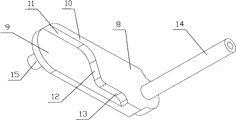
[0035] The three-dimensional structure diagram of the friction hinge support plate is as follows figure 2 As shown, wherein: 8 is a support plate, 9 is an open groove, 10 is a reinforced support rib, 11 is a first positioning locking surface, 12 is a second positioning locking surface, 13 is a third positioning locking surface, and 14 is a Fan fixed plate connects hinge shaft, and 15 is frame fixed plate hinge shaft. Fan fixed plate connecting hinge shaft 14 is made into one with support plate 8 and frame fixed plate hinge shaft 15 is ma...
Embodiment 2
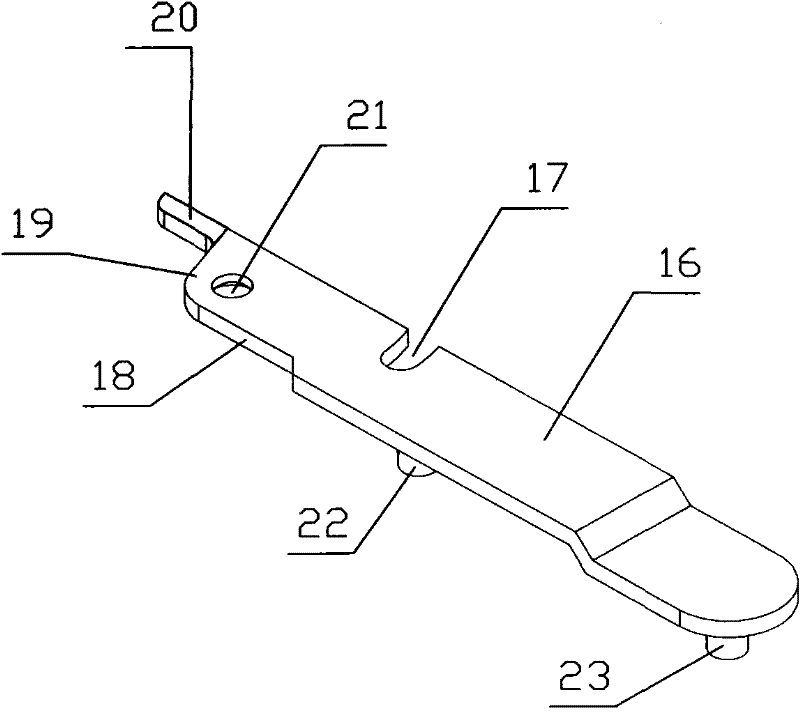
[0050] The three-dimensional structure diagram of the moving slider friction hinge frame fixed plate is as follows Figure 10 As shown, among them: 47 is the friction hinge frame fixing plate, 48 is the hinge hole of the sliding support plate, 49 is the guide groove of the moving slider, 50 is the lower guide groove of the moving slider, 51 is the frame fixing plate seat, 52 is the lower fixing tenon .
[0051] The three-dimensional structure diagram of the friction hinge support plate is as follows Figure 11 As shown, wherein: 53 is a support plate, 54 is an open groove, 55 is a reinforced support rib, 56 is a first positioning locking surface, 57 is a second positioning locking surface, 58 is a third positioning locking surface, and 59 is a The fan fixed plate connects the hinge shaft, 60 is the frame fixed plate hinge shaft, and 61 is a triangular positioning boss. Fan fixed plate connecting hinge shaft 59 is made into one with support plate 53 and frame fixed plate hing...
PUM
 Abstract
Description
Claims
Application Information