
Wind nozzle with easily operated tommy bar

An easy-to-operate, air-nozzle-head technology, which is applied to variable-capacity pump components, liquid variable-capacity machinery, machines/engines, etc., can solve the problems of not being a high-quality product, not a finished product, and not being used smoothly.

Active Publication Date: 2012-01-11
吴树木
View PDF4 Cites 2 Cited by
  • Summary
  • Abstract
  • Description
  • Claims
  • Application Information

AI Technical Summary

Problems solved by technology

[0005] It is very inconvenient to pull the lever 93 of the pump in the prior art. When the user wants to operate the lever 93 away from the pump body 91, the lever 93 needs to be pulled between the spokes, so that the user's hand will be affected. Due to the limitation, there will be the disadvantage of touching the spokes and causing interference, which will cause inconvenience in the operation of the lever 93, and the lever 93 is located on the side opposite to the cap 94, so the lever 93 is located on the pump when viewed by the user. Therefore, you must first grasp the trigger lever 93 and then pull the trigger lever 93. It is very difficult to use and needs to be improved.
[0006] Furthermore, the inflator lever 93 protrudes from the outer edge of the inflator 90, so that the overall peripheral edge of the inflator 90 is protruding, so that the lever 93 is easily touched or interferes with the tire valve. When the pump 90 is stored, because the protruding part exceeds the outer periphery of the pump 90, there will be a lack of space. The most important protruding part makes the whole pump 90 look like the design is not completed, that is, it is not a The finished product is not a high-quality product, and when the pump 90 is installed on a bicycle, the opposite sides of the pump 90 are restricted by the cap 94 and the lever 93 respectively, so there will be a disadvantage of being stuck on the bicycle frame. Inconvenient, there is a need to improve

Method used


Image

  • Wind nozzle with easily operated tommy bar
  • Wind nozzle with easily operated tommy bar
  • Wind nozzle with easily operated tommy bar

Examples


Embodiment Construction

[0052] Regarding the technology, means and effects used in the present invention, two preferred embodiments are given and described in detail below with drawings, which are for illustration purposes only, and are not limited by this structure in patent applications.

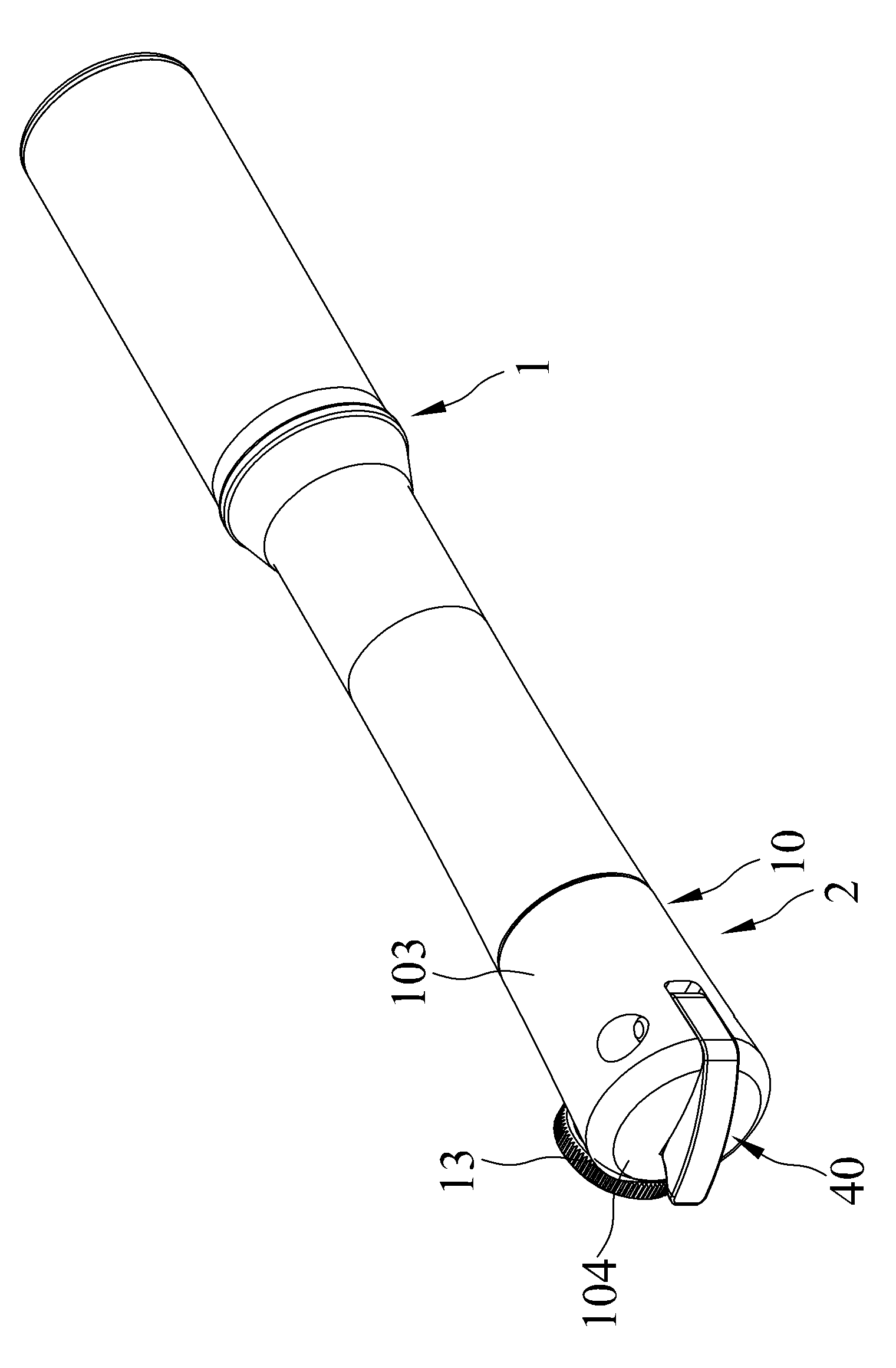
[0053] refer to figure 1 , is a three-dimensional appearance view of the pump of the present invention. The pump includes a pump body 1 and an air nozzle head 2. The pump body 1 can reciprocate for pumping operations. The air nozzle head 2 is located at one end of the pump body 1. The air nozzle head 2 and the pump body 1 are two separate parts One-piece structure, of course, the tuyere head 2 and the pump body 1 can also be an integral structure.

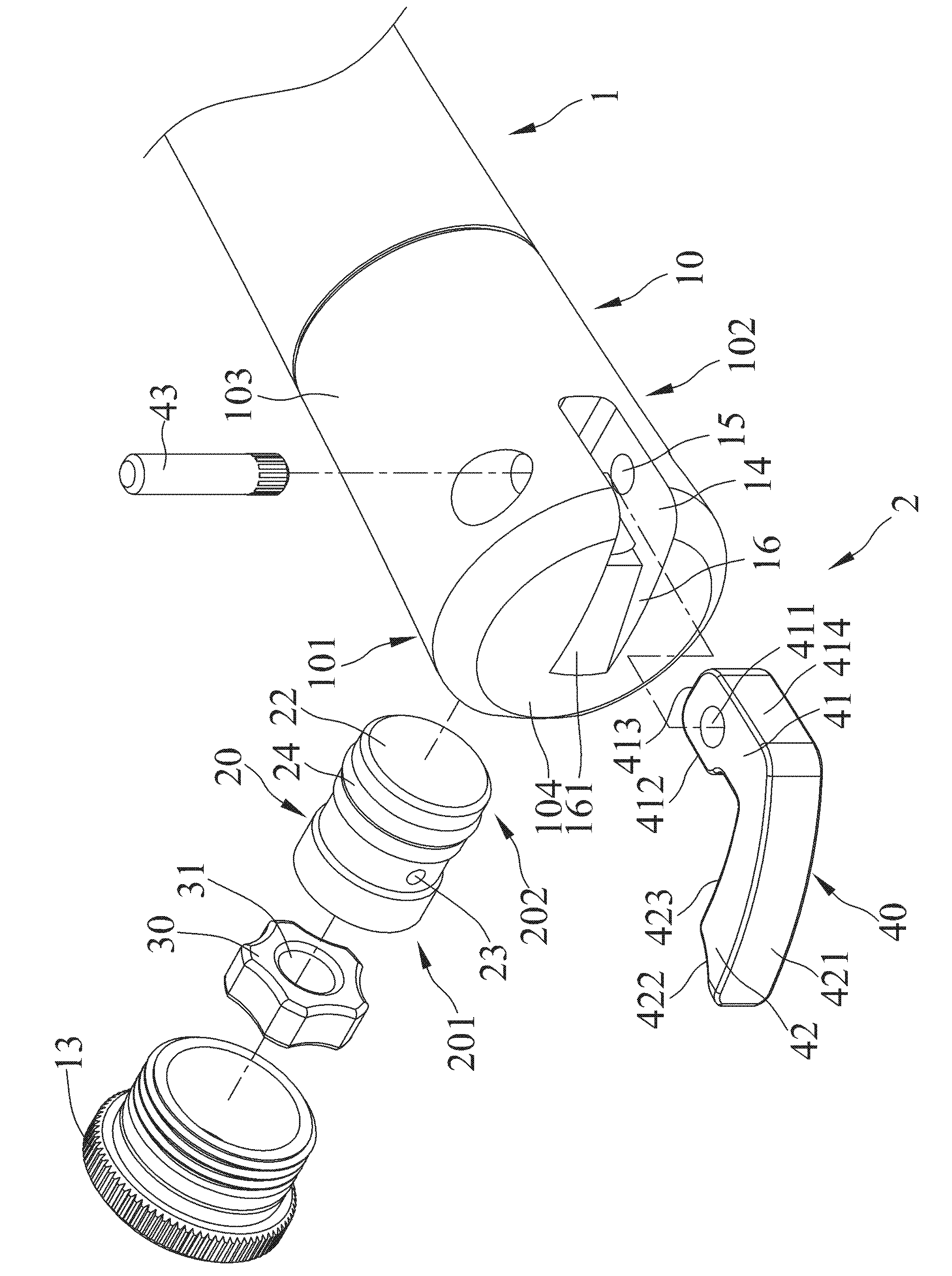
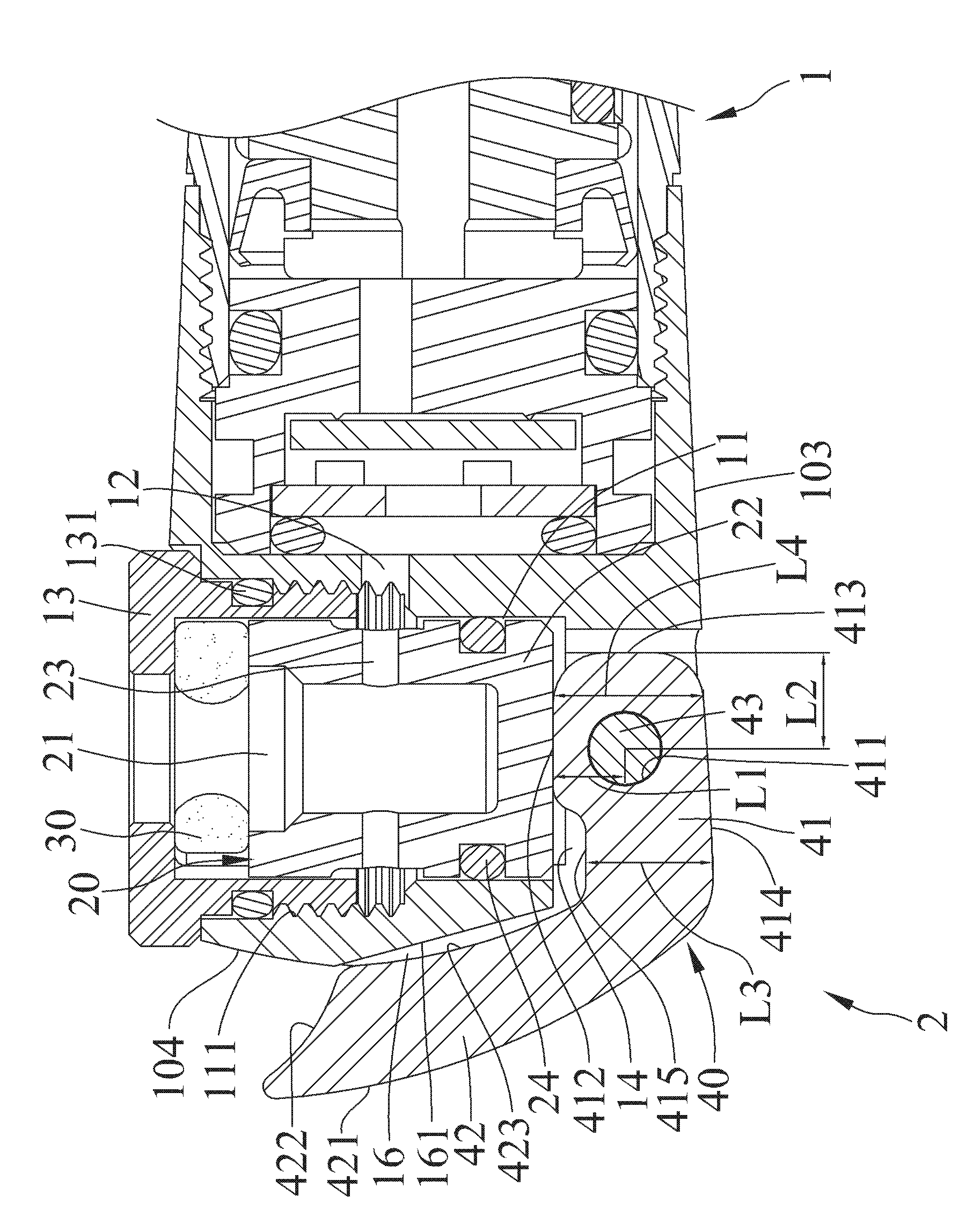
[0054] refer to figure 2 and image 3 , is a three-dimensional exploded view and a schematic cross-sectional view of the tuyere head with an easy-to-operate lever lever of the present invention. The nozzle head 2 of the present invention includes a body 10 , a cor...


PUM


Abstract

The invention provides a wind nozzle with an easily operated tommy bar, which comprises a body, a jack tube, a wind nozzle plug and a tommy bar. The body comprises an inner chamber and an accommodating chamber. The jack tube and the wind nozzle plug are inserted inside the inner chamber. The tommy bar comprises an eccentric cam part and a turning part. The eccentric cam part is pivoted on the accommodating chamber. The eccentric cam part is also accommodated inside the accommodating chamber. The eccentric cam part comprises a first outer surface. The turning part is connected with the eccentric cam part. The turning part comprises a turning face. The tommy bar can move between a loosening position and a fastening position. When the tommy bar is at the loosening position, the first outer surface of the eccentric cam part is corresponding to the outer surface of the body. When the turning part is out of the top face of the body, the turning face faces towards the nozzle end of the body.

Description

technical field [0001] The invention mainly discloses a nozzle head of an air pump, especially a nozzle head whose trigger rod does not protrude from the outer surface and is easy to operate. Background technique [0002] Common pumps are mainly divided into three categories, floor pumps, small pedal pumps and mini pumps. Among them, the reason why the mini pump is favored by consumers is that it is small in size and easy to carry. During the filling operation, it is necessary to hold the cylinder and the nozzle head of the pump with one hand in front of the other to let the pump produce air. [0003] However, the applicant has devoted himself to the pump field for many years and deeply feels that there is room for improvement in the mini pump. When the mini pump is inflated, the nozzle head of the pump will be connected to the gas nozzle of the object to be inflated, and the nozzle head of the mini pump is pivotally equipped with a lever, which is pushed against the center...

Claims


Application Information

Patent Timeline
IPC IPC(8): F04B39/00F04B33/00
CPCF04B33/005
Inventor 吴树木
Owner 吴树木
Features
  • Generate Ideas
  • Intellectual Property
  • Life Sciences
  • Materials
  • Tech Scout
  • Unparalleled Data Quality
  • Higher Quality Content
  • 60% Fewer Hallucinations
Learn More