
U-shaped sealing member

A seal, U-shaped technology, applied in engine seals, piston pump seals, pump components, etc., can solve problems such as insufficient seal stability, difficulty in application, and adverse effects on seal performance, and achieve durability and seal stability Excellent performance, low cost and manufacturing, and excellent sealing performance

Active Publication Date: 2015-07-22
MITSUBISHI CABLE IND LTD
View PDF7 Cites 0 Cited by
  • Summary
  • Abstract
  • Description
  • Claims
  • Application Information

AI Technical Summary

Problems solved by technology

[0007] However, when such conventional U-shaped seals are intended to be used as flat seals and applied to scroll compressors, etc., the sealing stability may be insufficient, and it is known that premature wear occurs, making it difficult to apply.
[0008] In particular, since the scroll of the scroll compressor performs eccentric rotation and slides against the above-mentioned protrusion 45, and the direction of the cutting tool mark on the surface of the scroll to be sealed is complicated by the above-mentioned eccentric rotation and the like. The combination of movement, etc., is likely to have an adverse effect on the sealing performance

Method used


Image

  • U-shaped sealing member
  • U-shaped sealing member
  • U-shaped sealing member

Examples


Embodiment Construction

[0033] Hereinafter, the present invention will be described in detail based on the illustrated embodiments.

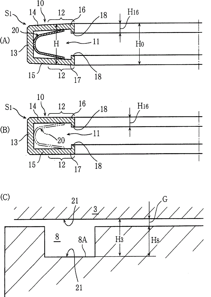
[0034] figure 1 In, the U-shaped seal S to which the present invention is applied is exemplified 1 , S 2 The sealing structure of the scroll compressor 2 seals the planar minute gap G between the scroll 3 performing the eccentric rotation M of the scroll compressor 2 and the fixed housing 4 .

[0035] figure 2 will be figure 1 The detailed diagram of the Y part is enlarged, as shown in the figure 1 as well as figure 2 As shown, with an axis L 4 Large diameter and small diameter U-shaped seals S are arranged concentrically at the center 1 , S 2 .

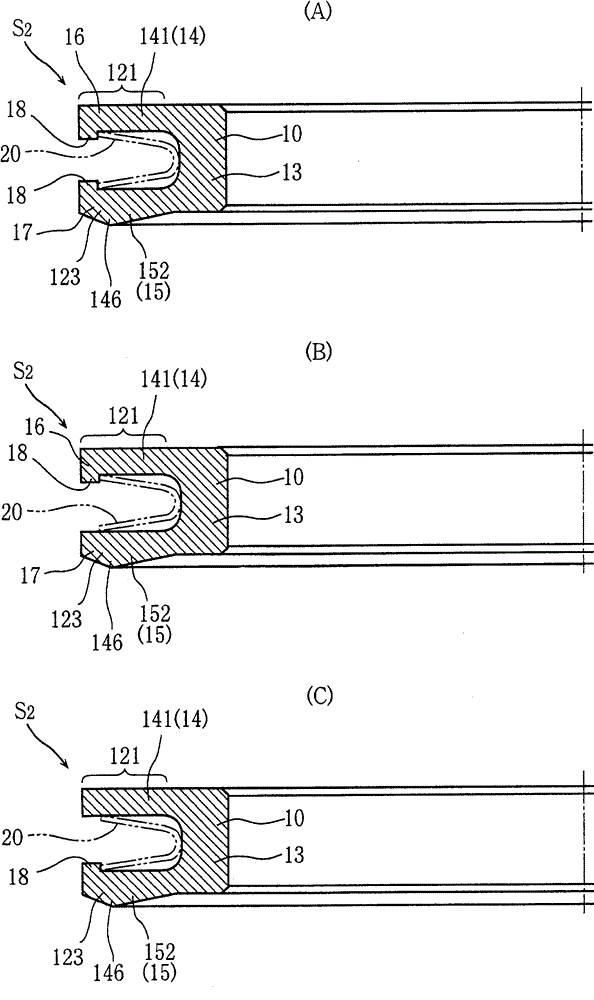
[0036] U-shaped seal S of the first embodiment 1 It opens radially inward and has a large diameter. The U-shaped seal S of the second embodiment 2 The opening radially outward is a small diameter. Sealed fluids are, for example, cooling media and oil. If along an axis L 4 look in the direction of figure 1...


PUM


Abstract

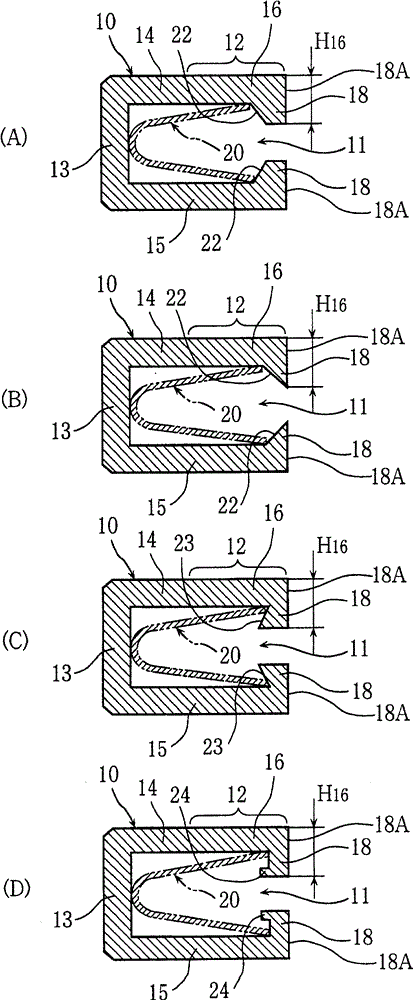
The invention provides a U-shaped sealing member which achieves excellent stability in terms of sealing of a sealed plane of a scroll compressor and so on which make eccentric rotation. The U-shaped sealing member comprises a sealing member body (10) which has a U-shaped cross section and is made of resin, and a built-in elastic body (20) which is placed in a groove (11) of the sealing member body (10) and is made of metal. The seal portion (12) (12) of the sealing member body (10) contacted with the sealed plane (21) (21) has no projecting portion and is in the shape of a flat plane.

Description

technical field [0001] The invention relates to a U-shaped seal. Background technique [0002] previously known Figure 12 U-shaped seal 41 is shown. That is, it has a seal body 42 made of synthetic resin and a metal inner spring 44 fitted into a groove 43 thereof. About the above Figure 12 As for the U-shaped packing 41 having the structure shown, the present applicant has previously proposed inventions shown in Patent Documents 1 and 2. [0003] The above-mentioned conventional U-shaped seal 41 serves as a rod seal and a piston seal, and has a groove 43 opening in a direction parallel to the rod axis, and further has protrusions 45 and 46 with triangular mountain-shaped cross-sections. [0004] Patent Document 1: Japanese Patent Laid-Open No. 2004-76870 [0005] Patent Document 2: Japanese Patent Application Laid-Open No. 8-82372 [0006] Such as Figure 12 As shown, due to the protrusions 45, 46 having triangular mountain-shaped ridges (in linear contact with the opp...

Claims


Application Information

Patent Timeline
Patent Type & Authority Patents(China)
IPC IPC(8): F16J15/18F04C27/00
Inventor 松浦王昭
Owner MITSUBISHI CABLE IND LTD
Learn More