Apparatus for detecting integrity of foundation pile by using acoustic transmission method and detection method used therein

A technology of integrity detection and transmission method, which is applied in the direction of using sound wave/ultrasonic wave/infrasonic wave to analyze solids, etc. It can solve the problems of inability to locate defect parts and low test efficiency, and achieve the effect of improving test efficiency and simplifying test procedures

Active Publication Date: 2012-01-11
北京市康科瑞工程检测技术有限责任公司 +2
View PDF3 Cites 33 Cited by
  • Summary
  • Abstract
  • Description
  • Claims
  • Application Information

AI Technical Summary

Problems solved by technology

[0003] The purpose of the present invention is to provide a sound wave transmission method foundation pile integrity detection device and the detection method adopted, to solve the problem that the existing sound wave transmission method can only complete the measurement line test in one direction in a full-height lifting test process of a section , the technical problem that it is impossible to spatially locate the defective part and the test efficiency is low

Method used


Image

  • Apparatus for detecting integrity of foundation pile by using acoustic transmission method and detection method used therein
  • Apparatus for detecting integrity of foundation pile by using acoustic transmission method and detection method used therein
  • Apparatus for detecting integrity of foundation pile by using acoustic transmission method and detection method used therein

Examples


Embodiment 1

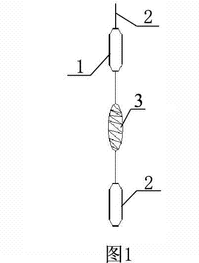
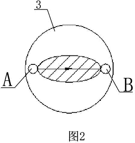
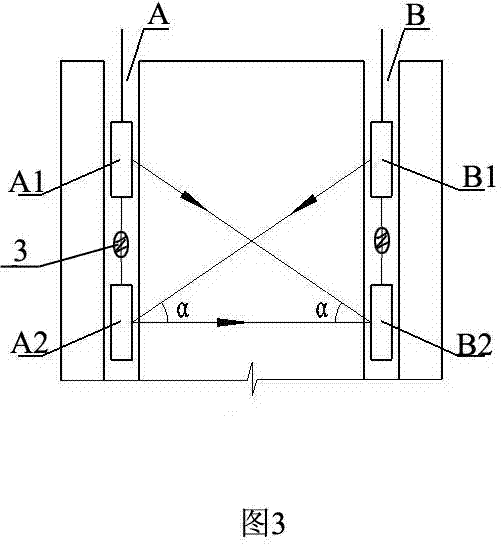
[0039] Embodiment one sees Figure 2 ~ Figure 3 As shown, the pile diameter of the foundation pile 2 to be tested is less than 800mm. Generally, two acoustic measuring tubes are buried, which are respectively acoustic measuring tubes A and B. There is a test section A-B. The test steps are as follows:

[0040] Step 1: Determine the distance between two adjacent radial transducers according to the distance between the two acoustic tubes, the angle between the horizontal line and the oblique line, and the sensitivity of the radial transducer; Change again; when the horizontal spacing of the acoustic tube is determined, increase the radial transducer spacing, so that the angle α between the oblique measurement line and the horizontal measurement line increases, and further moves closer to the orthogonal trend, which is beneficial to the two-dimensional test However, due to the directivity of the radial transducer on the vertical plane, the receiving response of the transducer dec...

Embodiment 2

[0049] Embodiment two see Figure 5 ~ Figure 8 When the pile diameter of the foundation pile to be tested is between 800mm and 1500mm, three acoustic tubes are generally buried, namely acoustic tube A, acoustic tube B and acoustic tube C, with three test sections: A-B, B-C and C-A.

[0050] The only difference from Example 1 is that 9 tests of 9 measuring lines are completed through 9 switches at each measuring point, including 3 flat tests and 6 oblique tests. If the instrument used for the test has the function of one send and two receive , the number of switching times can be reduced to 5: see Table 2 for details:

[0051] Table II

[0052]

[0053] The A1 and A2 represent the upper radial transducer and the lower radial transducer placed in the acoustic tube A, and the B1 and B2 represent the upper radial transducer and the lower radial transducer placed in the acoustic tube B radial transducer. The C1 and C2 represent the upper radial transducer and the lower radia...

Embodiment 3

[0054] Embodiment three see Figure 9 to Figure 15 , when the pile diameter of the foundation pile to be tested is greater than 1500mm, four acoustic test tubes are generally buried, namely acoustic test tube A, acoustic test tube B, acoustic test tube C and acoustic test tube D, with six test sections: A-B, B-C, C-D, D-A, B-D and A-C.

[0055] The only difference from Example 1 is that 18 tests of 18 measuring lines are completed at each measuring point, including 6 flat tests and 12 oblique tests. The number of times is reduced to 7: see Table 3 for details:

[0056] Table three

[0057]

[0058] The A1 and A2 represent the upper radial circular transducer and the lower radial transducer placed in the acoustic tube A, and the B1 and B2 represent the upper radial transducer and the lower radial transducer placed in the acoustic tube B radial transducer. The C1 and C2 represent the upper radial transducer and the lower radial transducer placed in the acoustic tube C. T...


PUM

PropertyMeasurementUnit
diameteraaaaaaaaaa

Abstract

The invention relates to an apparatus for detecting integrity of foundation piles by using the acoustic transmission method and a detection method used therein, belonging to the technical field of acoustic detection of foundation piles. According to the invention, simultaneous detection of measuring lines at a plurality of directions in the process of one full elevation lifting detection of a profile is realized by arranging at least two tandem radial energy transducers at cable terminals; the method has the advantages of simplified detection procedures and improved detection efficiency, is more favorable for spatial positioning of a defect part and can be extensively used in detection of integrity of foundation piles by using the transmission method.

Description

technical field [0001] The invention relates to a foundation pile integrity detection device and a detection method thereof, in particular to a foundation pile integrity detection device using an acoustic wave transmission method and a detection method thereof. Background technique [0002] At present, the pile foundation structure is widely used in the construction field. The integrity of the pile body in the structure has a very important impact on the safety of the building. The ultrasonic transmission method of the concrete pouring pile is a method widely used in the integrity detection of the pile body today. . Existing technical specifications for quality testing of foundation piles include national industry standards, association standards and local technical standards. 2003); (2) Standard of China Engineering Construction Standardization Association "Ultrasonic Method for Detection of Concrete Defects" (CECS 21:2000). The basic features of the on-site detection me...

Claims


Application Information

Patent Timeline
Patent Type & Authority Applications(China)
IPC IPC(8): G01N29/04
Inventor 濮存亭卫红刘彦林石银峰郜国忠郭启亮阚月鹏穆铁军李琳申强孟昭晖张伟
Owner 北京市康科瑞工程检测技术有限责任公司
Why Eureka
Try Eureka