
Multi-channel real-time monitoring and management system

A real-time monitoring and management system technology, applied in closed-circuit television systems, transmission systems, digital transmission systems, etc., can solve the problems of fixed cameras, no longer adapting to market demand, and enlarged monitoring screens, so as to achieve flexible use and fault management Maintain quick results

Inactive Publication Date: 2012-01-11
GUANGDONG XUNTONG TECH
View PDF2 Cites 20 Cited by
  • Summary
  • Abstract
  • Description
  • Claims
  • Application Information

AI Technical Summary

Problems solved by technology

[0005] With the continuous development of the current monitoring system, there are more and more monitoring devices in the monitoring system, so there are different degrees of troubles in the command control management and troubleshooting of a single device, such as: at a certain moment, the monitoring of a certain camera The angle of view and focal length need to be adjusted according to the needs of the manager, and the monitoring screen needs to be enlarged. Most of the current monitoring systems cannot do this, because the front-end cameras are fixed or can only rotate according to a predetermined trajectory. , the monitoring screen is also displayed according to the preset screen. If you want to zoom in, the usual measures are: call out the video data stored in the video recording unit, and then process it with a separate computer; another example: monitor a certain monitoring system Sudden failure, as long as the current picture is still there, it is not easy for the monitoring personnel to detect the static picture in time
[0006] It can be seen from the above that the existing monitoring system has deficiencies in the individual management and monitoring of each device in the monitoring network, and no longer meets the market demand.

Method used


Image

  • Multi-channel real-time monitoring and management system
  • Multi-channel real-time monitoring and management system

Examples


Embodiment Construction

[0033] The present invention will be described in detail below in conjunction with the accompanying drawings and specific embodiments, where the schematic embodiments and descriptions of the present invention are used to explain the present invention, but not to limit the present invention.

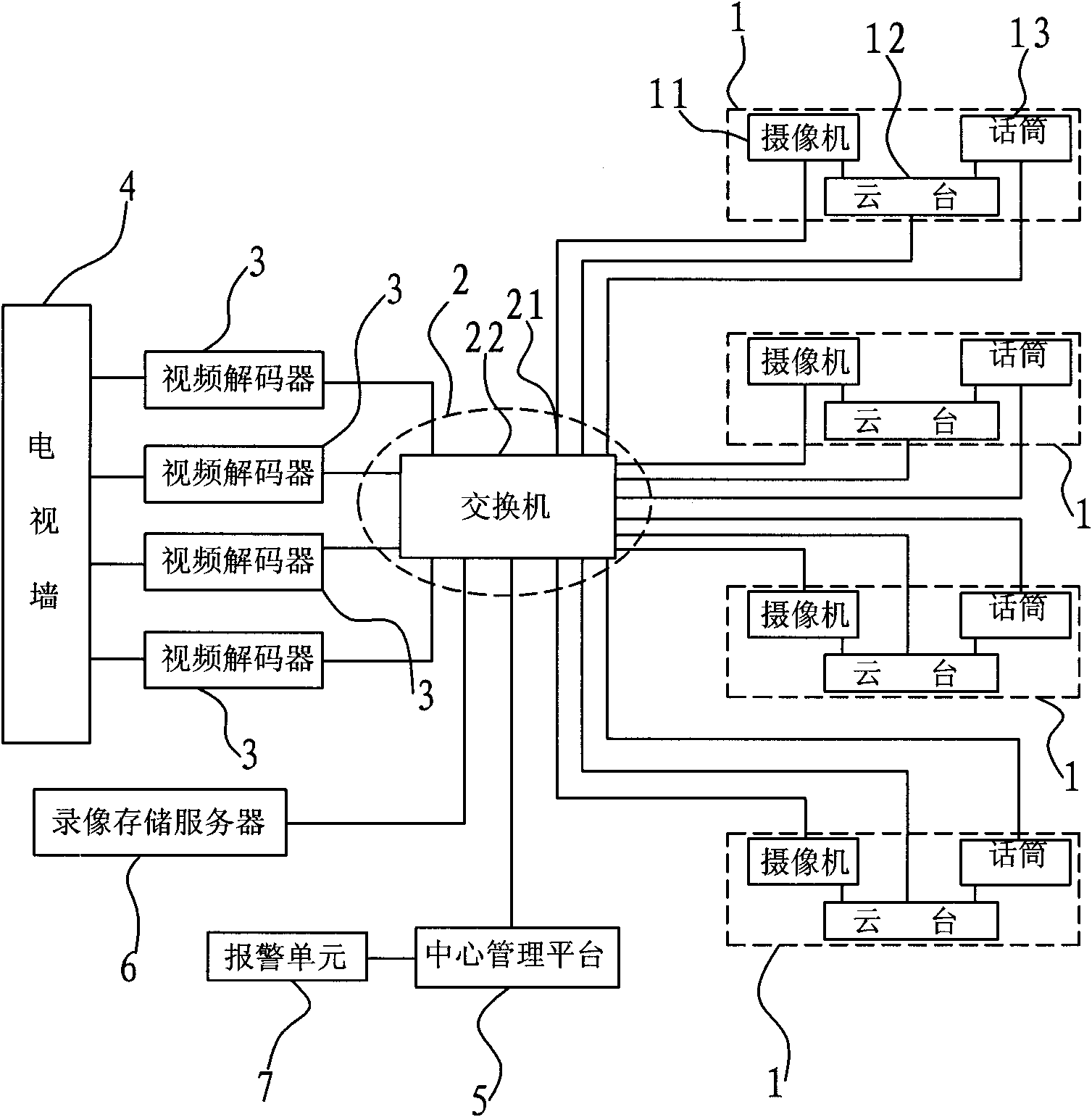
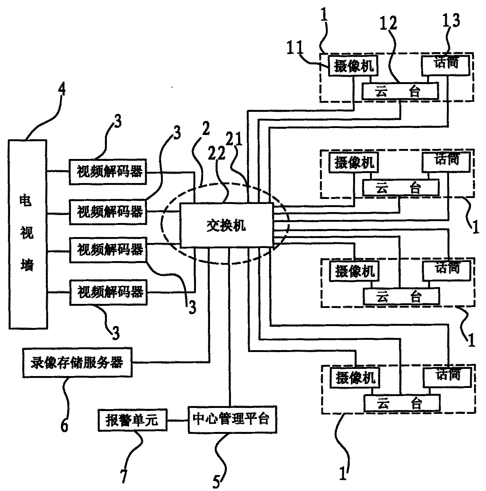
[0034] The invention discloses a multi-channel real-time monitoring and management system, such as figure 1 As shown, it includes four-channel front-end audio and video acquisition equipment 1, intermediate transmission network 2, four-channel video decoder 3, video wall 4, central management platform 5, video storage server 6, and alarm unit 7.

[0035] Described front-end audio and video acquisition equipment 1 comprises video camera 11, and the cloud platform 12 that is installed on this video camera 11, microphone 13, wherein microphone 13 and video camera 11 gather and monitor scene audio information and video information and obtain one road audio and video signal, and all The audio ...


PUM


Abstract

The invention belongs to the technical field of monitoring, and in particular discloses a multi-channel real-time monitoring and management system. The system comprises at least one front-end audio-video capture device, an intermediate transport network, at least one video decoder, a television wall and a central management platform, wherein a duplex communication manner is adopted between the central management platform and other equipment; and the central management platform issues instructions to the other equipment so as to manage and control operation of the other equipment; meanwhile, the central management platform collects the running status data of the other equipment so as to facilitate monitoring and management of the equipment. The system provided by the invention has the advantages that any one front-end supervising device and back-end display device can be instructed randomly so as to realize more flexible application; meanwhile the system also has the advantage of more rapid fault management and maintenance.

Description

technical field [0001] The invention belongs to the technical field of monitoring, and in particular relates to a multi-channel real-time monitoring management system. Background technique [0002] A typical TV monitoring system is mainly composed of front-end monitoring equipment, transmission equipment, and back-end control and display equipment. The three parts form a monitoring network with each other. The front-end and back-end equipment can be constructed in a variety of ways, and the connection between them (also called a transmission system) can be realized through various methods such as cables, optical fibers, or microwaves. [0003] Among them, the front-end acquisition system usually includes cameras, lenses, pan-tilts, and smart dome cameras; the video transmission system includes transmission cables, optical fiber transmission, coaxial cable transmission, network cable transmission, and wireless transmission; the terminal display system includes hard disk video...

Claims


Application Information

Patent Timeline
IPC IPC(8): H04N7/18H04N7/26H04N5/232H04L12/24H04L12/26H04N19/44
Inventor 陈色桃
Owner GUANGDONG XUNTONG TECH
Learn More