Light-emitting module

A light-emitting module and light-emitting shaft technology, applied in optics, light guides, electric light sources, etc., can solve the problems of the dark light field of the light guide plate, the inability to effectively improve the light utilization rate, and the insufficient brightness uniformity of the light guide plate. The effect of reducing product cost and energy waste and improving utilization rate

Inactive Publication Date: 2012-01-18
SHANGHAI XIANGLONG ELECTRONICS TECH
View PDF4 Cites 2 Cited by
  • Summary
  • Abstract
  • Description
  • Claims
  • Application Information

AI Technical Summary

Problems solved by technology

[0004] In this way, when the main light-emitting axis of the LED component is perpendicular to the outer side of the light guide plate that can show its thickness, the main light-emitting axis of the LED component will pass through the light guide plate, which cannot effectively improve the light utilization rate, resulting in a dark light field at the corner of the light guide plate The problem, resulting in insufficient brightness uniformity of the overall light guide plate

Method used


Image

  • Light-emitting module
  • Light-emitting module
  • Light-emitting module

Examples


no. 1 example

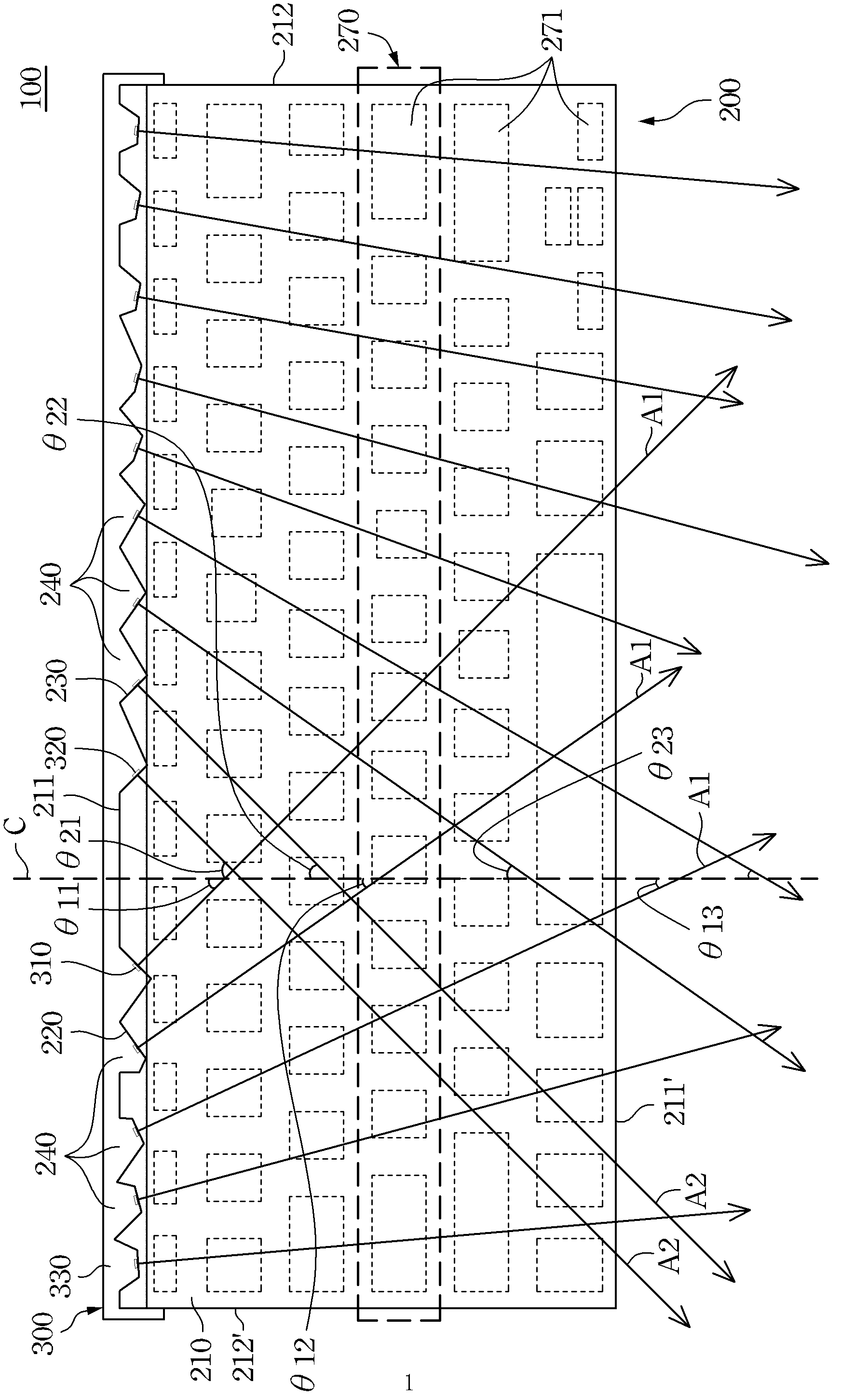
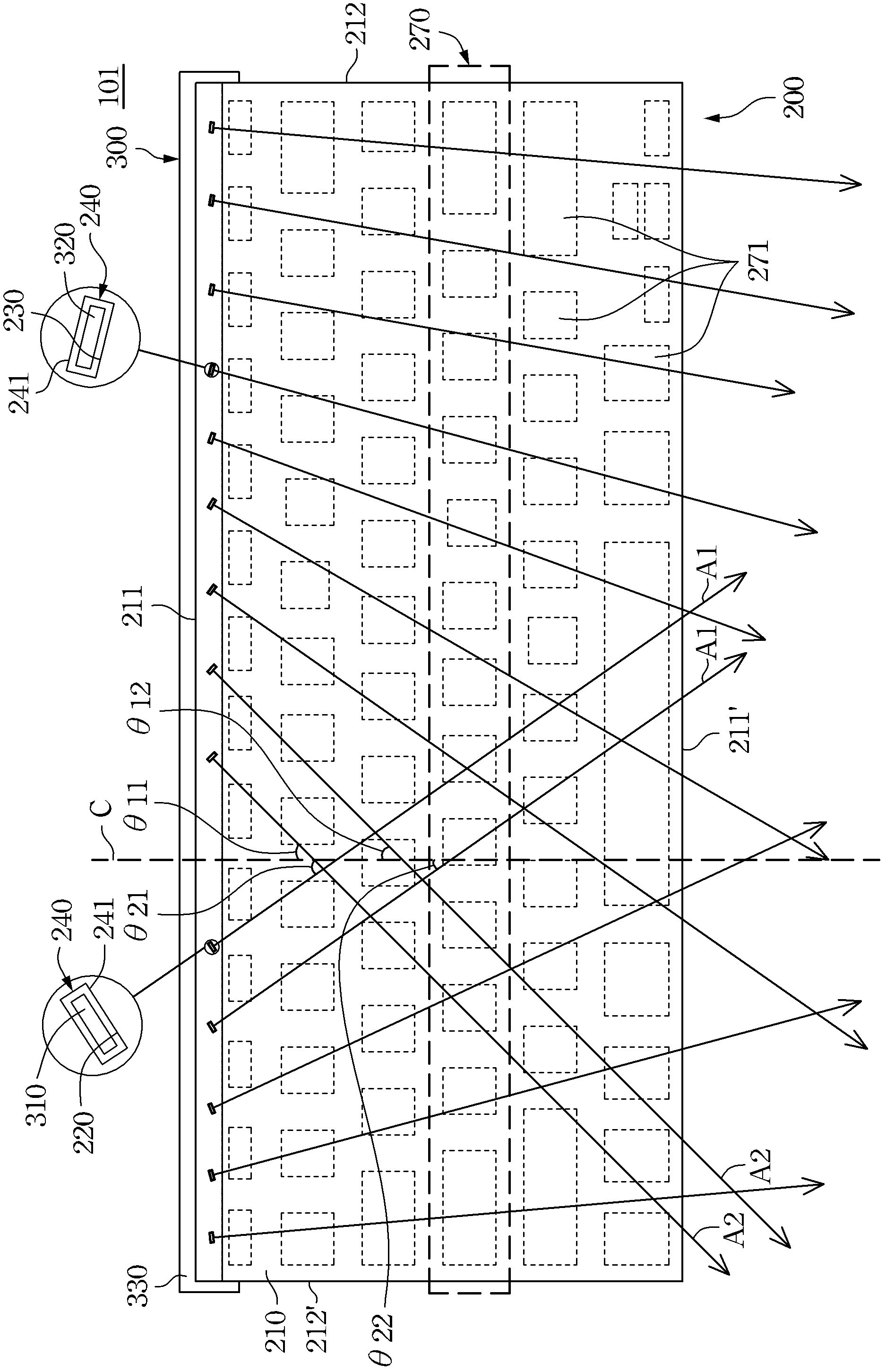
[0040] see again Figure 1Ashown. In the first embodiment of the present invention, the first light incident surface 220 and the second light incident surface 230 are arranged together on the outer side 211 of one of the long sides of the light exit surface 210 . For example, the outer side 211 of the long side of the light-emitting surface 210 includes a plurality of open first notches 240, and these first notches 240 are arranged at intervals along the extending direction of the outer side 211 of the long side, that is, on the outer side of the long side 211 presents an irregular jagged shape. The first light-incident surfaces 220 and the second light-incident surfaces 230 are respectively located in the first notches 240 one by one, and are arranged at intervals along the extending direction of the outer side 211 of the long side. However, in this first embodiment, the first notches 240 can also be a closed slot respectively, and are arranged at intervals on the outer side...

no. 2 example

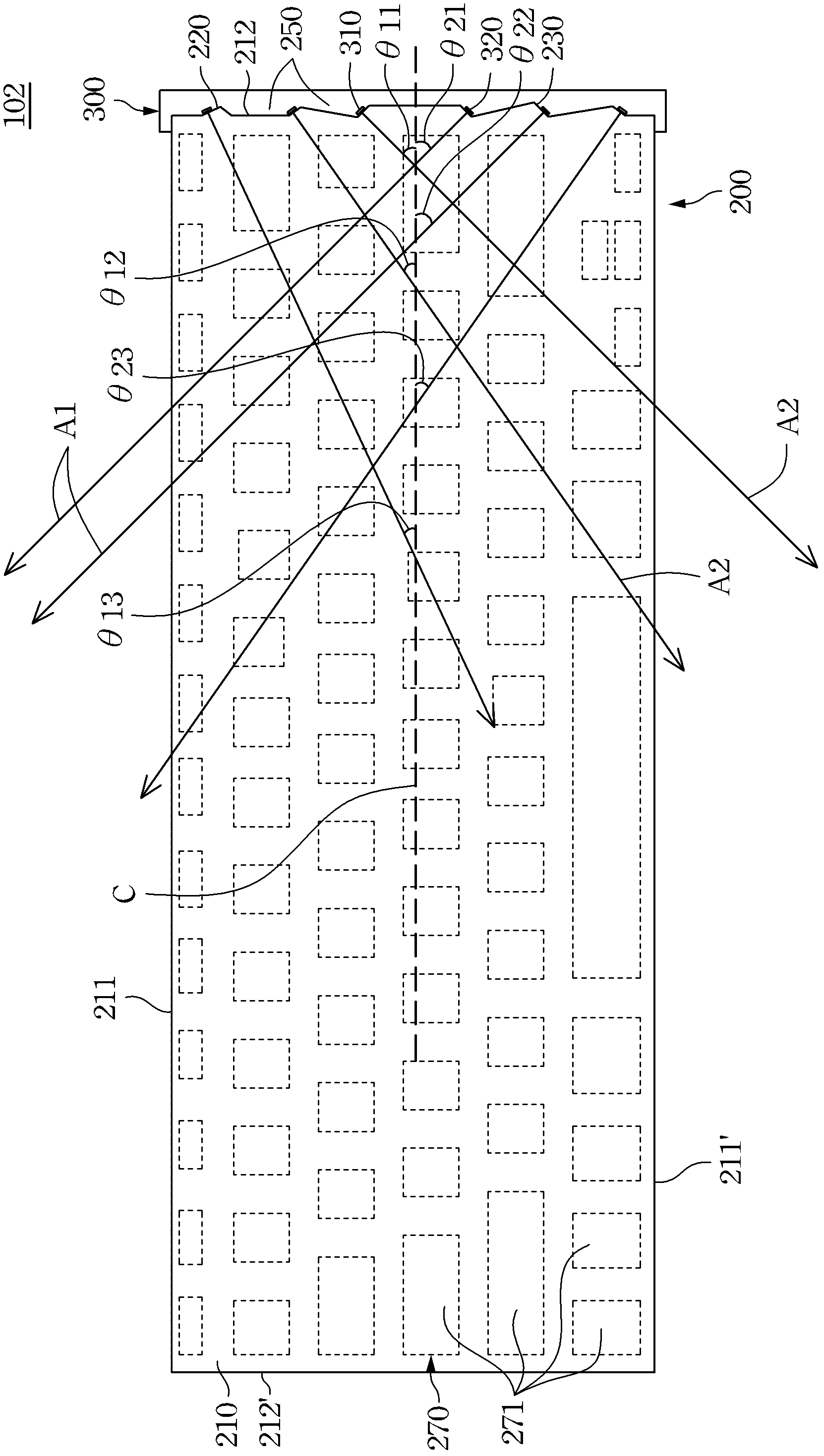
[0052] In the second embodiment of the present invention, the first light incident surface 220 and the second light incident surface 230 are arranged together on the outer side 212 of one of the short sides of the light exit surface 210 . For example, the outer side 212 of the short side of the light-emitting surface 210 includes a plurality of open second notches 250, and these second notches 250 are arranged at intervals along the extension direction of the outer side 212 of the short side, that is, on the outer side of the short side 212 presents an irregular jagged shape. The first light-incident surfaces 220 and the second light-incident surfaces 230 are respectively located in the second notches 250 one by one, and are arranged at intervals along the extension direction of the outer side 212 of the short side. However, in the second embodiment, the second notches 250 can also be a closed slot respectively, and are arranged at intervals on the outer side 212 of the short ...

no. 4 example

[0077] In the fourth embodiment of the present invention, the first light incident surface 220 and the second light incident surface 230 are co-arranged at an inner position 214 of the light exit surface 210 . The inner position 214 may be located on the light emitting surface 210 approximately across the midpoint of the outer short sides 212, 212'.

[0078] For example, the inner position 214 of the light-emitting surface 210 includes a plurality of closed fourth notches 280, such as the slots described in the first embodiment and the second embodiment, and these fourth notches 280 are along one of them. The extending directions of the outer sides 211' of the long sides are arranged at intervals. The first light-incident surfaces 220 and the second light-incident surfaces 230 are respectively located in the fourth notches 280 one by one, and are arranged in the interior of the light-emitting surface 210 at intervals along the extending direction of the outer side 211 of the l...


PUM


Abstract

The invention relates to a light-emitting module which comprises a light guide plate, a plurality of first light-emitting components and at least one second light-emitting component, wherein the light guide plate comprises a side edge, a plurality of first incident faces and at least one second incident face, the first incident faces, together with the at least one second incident face, are arranged at intervals along the extension direction of the side edge, and the first incident faces and the at least one second incident face are separated by a virtual phantom line; the plurality of first light-emitting components emit light towards the first incident faces respectively; the at least one second light-emitting component emits light towards the at least one second incident face; the main light emitting axes of the first light-emitting components are respectively staggered with the main light emitting axis of one of the at least one second light-emitting component, and the size of the inclined angle between the main light emitting axis of each first light-emitting component and the virtual phantom line is in inverse proportion to the distance from each first light-emitting component and the virtual phantom line; thus the utilization rate of light in the light guide plate is increased.

Description

technical field [0001] The invention relates to a light emitting module, in particular to a structure for increasing the light utilization rate of the light emitting module. Background technique [0002] With the development of technology, the design of computer keyboards is becoming more and more diversified. In addition to considering the functions of the products, the visual effects of the products will also affect the sales to some extent and are getting more and more attention. For example, the current keyboards on the market are equipped with light-emitting modules to become a light-emitting keyboard. In addition to being visually appealing, illuminated keyboards can also be used at night or in places with low lighting. A traditional light emitting module includes a light guide plate and a light source. The light source is composed of a plurality of light emitting diode elements (LED). These light emitting diode components are located outside the thickness of the li...

Claims


Application Information

Patent Timeline
Patent Type & Authority Applications(China)
IPC IPC(8): F21S8/00F21V8/00F21V23/00
Inventor 林育政
Owner SHANGHAI XIANGLONG ELECTRONICS TECH
Why Eureka
Try Eureka