
Dynamic balance correcting method for fan

A correction method and fan technology, applied in the static/dynamic balance test, machine/structural component test, measuring device, etc., can solve the problems of enterprise loss, increase of production and operation cost, consumption of large manpower and material resources, etc., to reduce production The effect of reducing operating costs, prolonging the maintenance and replacement cycle, and saving manpower and material resources

Inactive Publication Date: 2012-01-18
SICHUAN CHUANWEI GRP CO LTD +1
View PDF4 Cites 20 Cited by
  • Summary
  • Abstract
  • Description
  • Claims
  • Application Information

AI Technical Summary

Problems solved by technology

[0002] During the use of the fan, the dynamic balance of the fan is often damaged. After the dynamic balance of the fan is damaged, it usually needs to be corrected before it can continue to be used. At present, the dynamic balance of the fan is generally corrected by using a dynamic balancing machine. This method There are the following problems in the calibration process: First, when using a dynamic balancing machine to calibrate the dynamic balance of the fan, the impeller of the fan must be removed and then installed on the dynamic balancing machine to perform calibration. After the calibration is completed, the impeller must be installed on the On the fan, however, it takes a long time to disassemble and assemble the fan impeller. During the calibration process of the impeller, the fan cannot work, so that the production cannot be carried out normally, resulting in a shutdown. Moreover, the disassembly and assembly of the impeller requires a lot of manpower and material resources, which greatly This increases the cost of production and operation. Secondly, due to the high price of dynamic balancing machines, many manufacturers are not equipped with dynamic balancing machines. Once the dynamic balance of the fan is damaged, the impeller can only be removed and sent to the fan manufacturer for dynamic balance correction. It takes longer, which seriously affects the normal production of the enterprise and brings huge losses to the enterprise, and the cost of sending it back to the manufacturer for correction is also high, which increases the production and operation costs

Method used


Image

  • Dynamic balance correcting method for fan
  • Dynamic balance correcting method for fan
  • Dynamic balance correcting method for fan

Examples


specific Embodiment

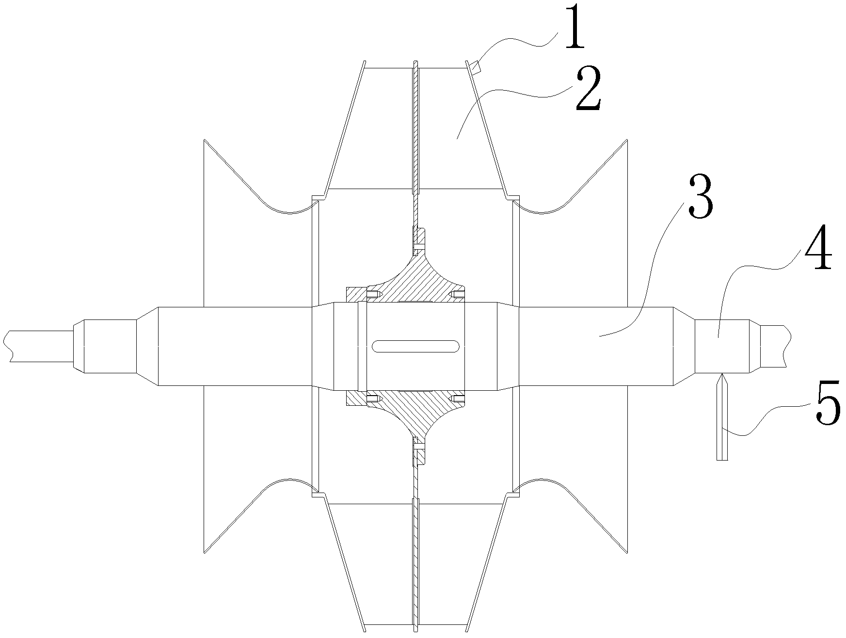
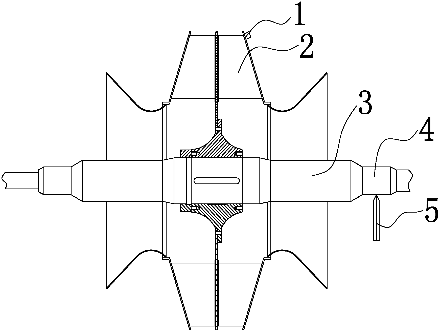
[0027] Specific embodiment: the quality M=10000kg of a blower fan impeller 2, the radius r=1200mm of impeller 2, the operating speed n=1000r / min of impeller 2, the balance grade is G6.3, the dynamic balance of this blower fan is destroyed, First, determine the unbalance point of the fan, and use the vibrometer to measure the radial vibration displacement of the fan due to unbalance △ = 0.10mm, and then calculate the allowable unbalance of the fan eper = (G×1000) / (n / 10)=(6.3×1000) / (1000 / 10)=63μm, the allowable residual unbalance of the fan m=(eper×M) / (r×2)=(63×10000) / (1200×2 )=262.5g, then calculate the unbalanced amount of the fan m″=(m / 0.13)×△=the unbalanced amount of the fan m″=(262.5 / 0.13)×0.10=201.9g, after calculating the unbalanced amount m″ of the fan, cut A counterweight 1 with a weight of 201.9g is fixed at the non-working position of the impeller 2 at an unbalanced point corresponding to an angle of 180° to balance the fan.


PUM


Abstract

The invention discloses a dynamic balance correcting method for a fan, which can be used for shortening the correcting time. The method comprises the following steps of: firstly, determining an imbalance point of the fan and measuring the radial vibration offset delta caused by imbalance of the fan by using a vibration measurer; secondly, computing allowed imbalance degree and allowed residual imbalance amount of the fan, wherein the allowed imbalance degree eper of the fan is equal to (G*1000) / (n / 10), and the allowed residual imbalance amount m of the fan is equal to (eper*M) / (r*2); thirdly,computing the imbalance amount of the fan, wherein the imbalance amount m'' of the fan is equal to (m / 0.13)*delta; and lastly, balancing. After the method is adopted for correcting the dynamic balance of the fan, the correcting time can be shortened greatly, the fan restores running within a very short period of time, normal performance of production is ensured, a large quantity of manpower and material resources are saved simultaneously, and the production running cost is lowered. The method is suitable to be popularized and applied in the fan repair field.

Description

technical field [0001] The invention relates to the field of fan maintenance, in particular to a method for correcting the dynamic balance of a fan. Background technique [0002] During the use of the fan, the dynamic balance of the fan is often damaged. After the dynamic balance of the fan is damaged, it usually needs to be corrected before it can continue to be used. At present, the dynamic balance of the fan is generally corrected by using a dynamic balancing machine. This method There are the following problems in the calibration process: First, when using a dynamic balancing machine to calibrate the dynamic balance of the fan, the impeller of the fan must be removed and then installed on the dynamic balancing machine to perform calibration. After the calibration is completed, the impeller must be installed on the On the fan, however, it takes a long time to disassemble and assemble the fan impeller. During the calibration process of the impeller, the fan cannot work, so...

Claims


Application Information

Patent Timeline
IPC IPC(8): G01M1/38
Inventor 兰东杨德朝伍连方陈洪春
Owner SICHUAN CHUANWEI GRP CO LTD
Learn More