Linear platform using compound bending vibration type biped linear ultrasonic vibrator

A linear ultrasonic and bending vibration technology, applied in the field of linear platforms, can solve the problems of low positioning accuracy and complex structure, and achieve the effects of high positioning accuracy, simplified mechanism, and simple structure

Active Publication Date: 2013-10-09
HARBIN INST OF TECH
View PDF5 Cites 0 Cited by
  • Summary
  • Abstract
  • Description
  • Claims
  • Application Information

AI Technical Summary

Problems solved by technology

[0004] The purpose of the present invention is to solve the problems of complex structure and low positioning accuracy existing in the linear platform driven by electromagnetic motors, and to provide a linear platform using a composite bending vibration biped linear ultrasonic vibrator

Method used


Image

  • Linear platform using compound bending vibration type biped linear ultrasonic vibrator
  • Linear platform using compound bending vibration type biped linear ultrasonic vibrator
  • Linear platform using compound bending vibration type biped linear ultrasonic vibrator

Examples


specific Embodiment approach 1

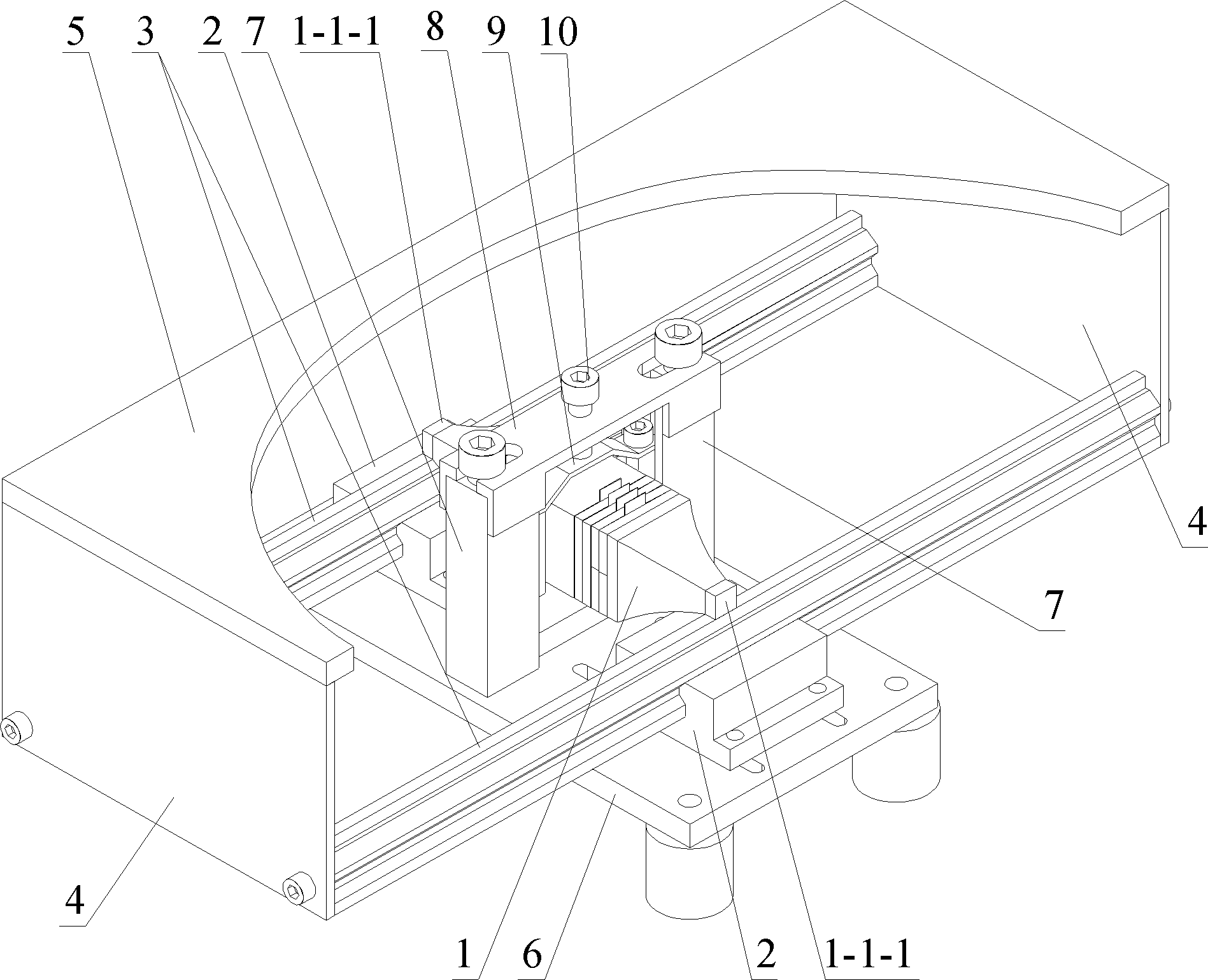
[0029] Specific implementation mode one: the following combination Figure 1 to Figure 7 Describe this embodiment, the linear platform using the compound bending vibration biped linear ultrasonic vibrator described in this embodiment, it includes a vibrator 1, two linear guide rails 2, two movers 3, two baffles 4, a platform 5, a base Seat 6, two positioning frames 7, preload beam 8, leaf spring 9 and preload screw 10,

[0030] Two linear guide rails 2 are arranged in parallel on the upper surface of the base 6, each linear guide rail 2 is provided with a mover 3, and one side end of the two mover 3 along the moving direction is fixedly connected with a baffle plate 4, The other ends of the two movers 3 along the moving direction are fixedly connected to the other baffle 4, and the platform 5 is fixedly connected to the upper end surfaces of the two baffles 4,

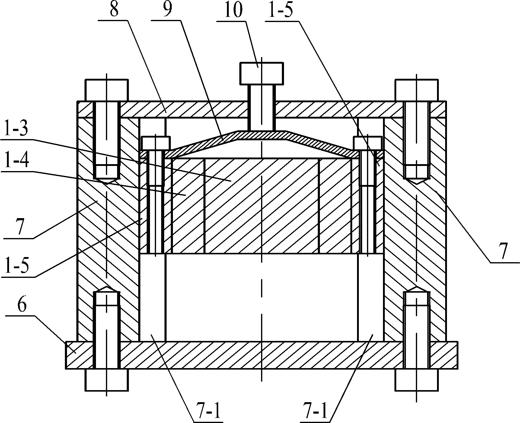
[0031] The pre-compression beam 8 is fixed on the base 6 through two positioning frames 7, the pre-compression beam...

specific Embodiment approach 2

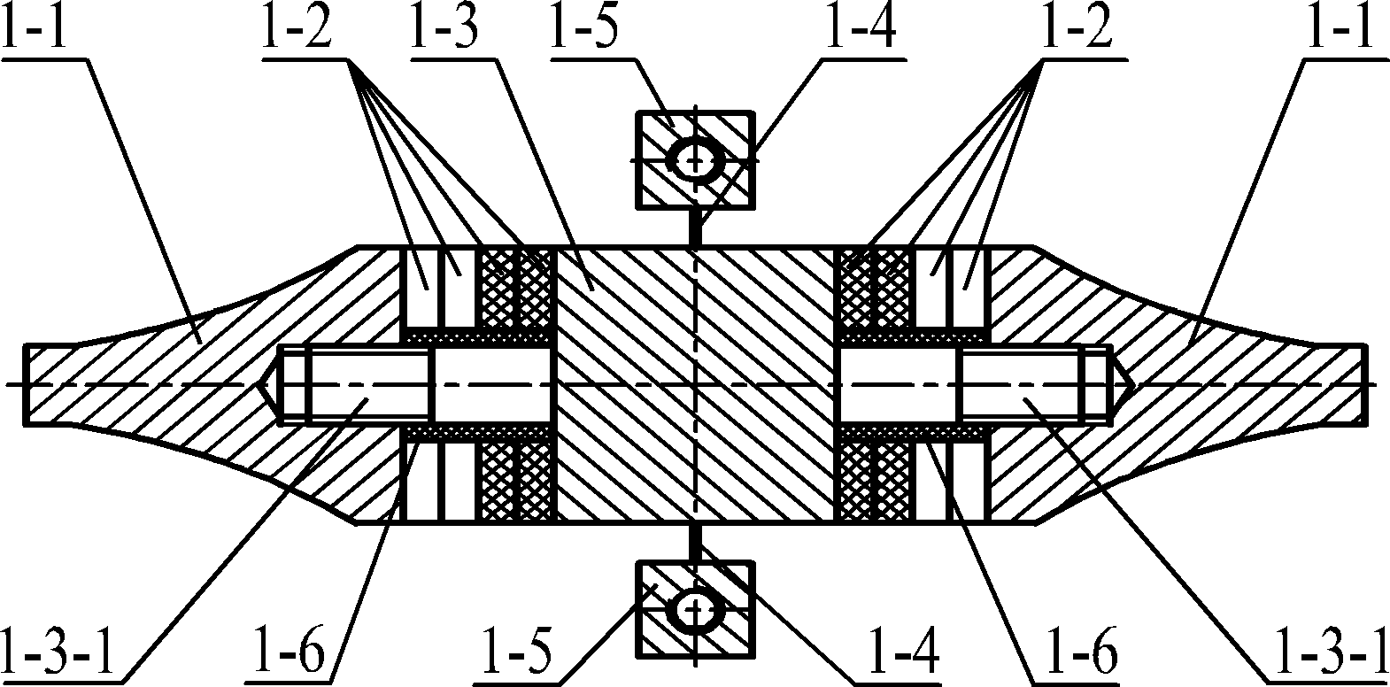
[0036] Specific implementation mode two: the following combination Figure 3 to Figure 7 Describe this embodiment, this embodiment is a further description of Embodiment 1, the vibrator 1 also includes two end caps 1-1, eight bending vibration piezoelectric ceramic sheets 1-2, flanges 1-3, two a thin-walled beam 1-4, two insulating sleeves 1-6, eight electrode sheets 1-7 and two friction sheets 1-8,

[0037] The two mounting seats 1-5 are arranged symmetrically on both sides of the flange 1-3, and each mounting seat 1-5 is fixedly connected to the flange 1-3 through a thin-walled beam 1-4.

[0038] A stud 1-3-1 is set in the center of the two end faces of the flange 1-3, and each stud 1-3-1 is covered with four pieces of bending vibration piezoelectric ceramic sheets 1-2, and the stud 1-3-1 An insulating sleeve 1-6 is arranged between 3-1 and the socket surfaces of the four bending vibration piezoelectric ceramic sheets 1-2, and between the end face of the flange 1-3 and the ...

specific Embodiment approach 3

[0044] Embodiment 3: This embodiment is a further description of Embodiment 1 or 2. The cross-section of the bending vibration piezoelectric ceramic sheet 1-2 is square or circular.


PUM


Abstract

The invention relates to a linear platform using a compound bending vibration type biped linear ultrasonic vibrator, belonging to the technical field of piezoelectric ultrasound drive. The problems of complex structure, low positioning accuracy and the like existing in the traditional linear platform driven by an electromagnetic motor are solved. The linear platform provided by the invention comprises a vibrator, two linear guide rails, two rotors, two baffle plates, a platform, a pedestal, two positioning frames, a prepressing beam, a plate spring and prepressing screws, wherein two linear guide rails are arranged on the upper surface of the pedestal in parallel, and each linear guide rail is provided with one rotor; one side end of each rotor in the direction of movement is fixedly connected with one baffle pate, and the other side end of each rotor in the direction of movement is fixedly connected with the other baffle pate; the platform is fixedly connected with the upper end faces of the two baffle plates; and the prepressing beam is fixed on the pedestal through the two positioning frames, is higher than the rotors and is located between the two rotors. The linear platform provided by the invention adopts an ultrasonic vibrator.

Description

technical field [0001] The invention relates to a linear platform using a composite bending-vibration biped linear ultrasonic vibrator, which belongs to the technical field of piezoelectric ultrasonic drive. Background technique [0002] The linear stage is the most commonly used equipment in the field of machinery manufacturing and precision instruments. At present, most of the mature linear stages use rotary electromagnetic motors as the driving components, and the rotary motion of the electromagnetic motor is converted into the linear motion of the working platform through the screw nut mechanism. ; Due to the use of the conversion mechanism, the system is more complicated, and the positioning accuracy of the platform will be reduced to a certain extent. [0003] The linear ultrasonic motor uses the inverse piezoelectric effect of piezoelectric ceramics to excite vibrations in the ultrasonic frequency range in the elastic body, and forms a particle motion with a specific ...

Claims


Application Information

Patent Timeline
Patent Type & Authority Patents(China)
IPC IPC(8): H02N2/02H02N2/04
Inventor 刘英想陈维山刘军考石胜君
Owner HARBIN INST OF TECH
Why Eureka
Try Eureka