Silencer support frame welding mold

A welding mold and muffler technology, applied in welding equipment, auxiliary welding equipment, welding/cutting auxiliary equipment, etc., can solve the problems of increasing processing cost, high welding rejection rate, low production efficiency, etc., to save production and use cost, ensure shape and position accuracy, and improve work efficiency

Inactive Publication Date: 2012-01-25
CHONGQING BEIBEI DISTRICT FENGHUO MACHINERY MFG
View PDF7 Cites 16 Cited by
  • Summary
  • Abstract
  • Description
  • Claims
  • Application Information

AI Technical Summary

Problems solved by technology

For the welding between small parts, the self-weight is light, and the positioning effect is not good, which is prone to deviation
Unlike other connection methods, welding is a non-detachable connection. If there is a large accuracy error, it will affect the quality of the entire product and even be scrapped.
[0003] In the prior art, the welding between the various parts of the small muffler requires relatively precise precision standards to ensure that there is no interference between the various parts when the muffler is installed; especially in the process of welding the installation bracket of the muffler, it is generally necessary Based on the experience of the operator to ensure the shape and position error, generally the spot welding is positioned first, and then the overall welding is performed, which makes the production efficiency low, the welding processing scrap rate is high, the processing cost is increased, and the labor intensity is increased.
Since the accuracy cannot be guaranteed, various forms of additional stress will appear after the muffler is installed, resulting in a low service life of the muffler installation structure and prone to failure

Method used


Image

  • Silencer support frame welding mold
  • Silencer support frame welding mold
  • Silencer support frame welding mold

Examples


Embodiment Construction

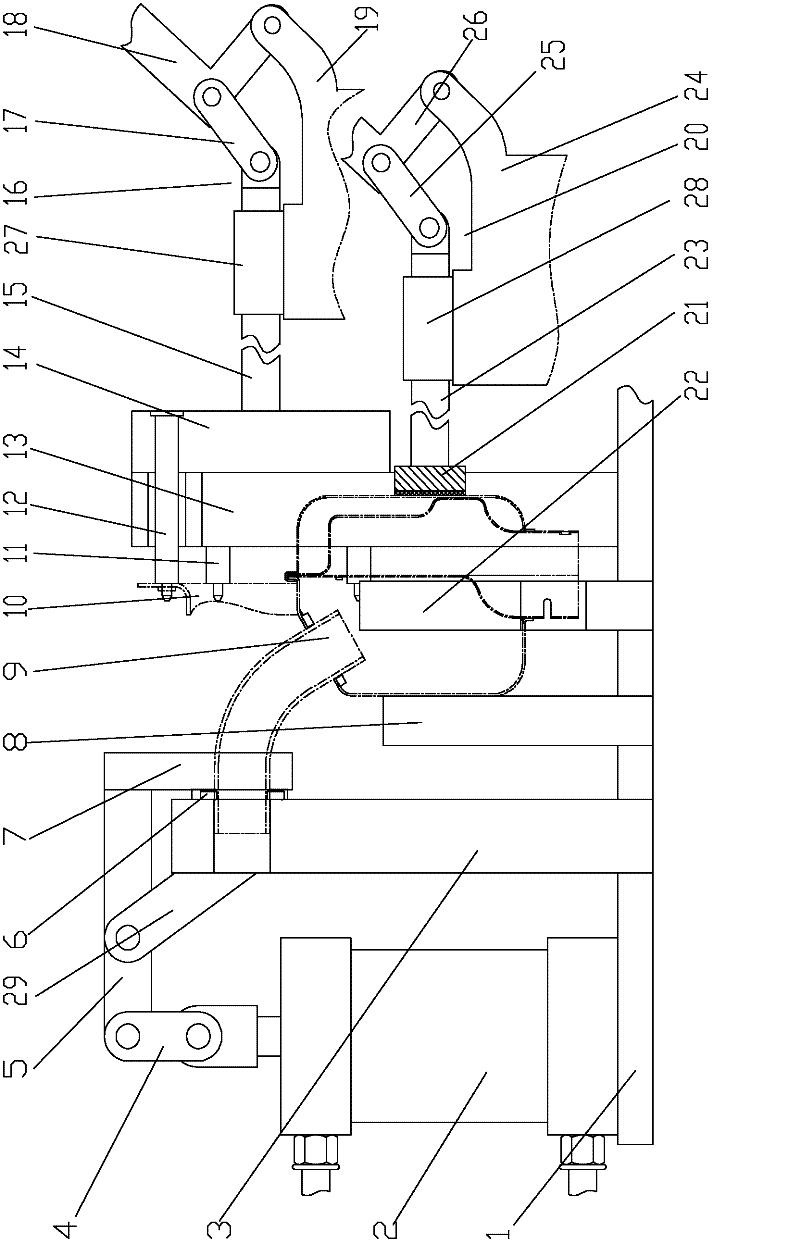
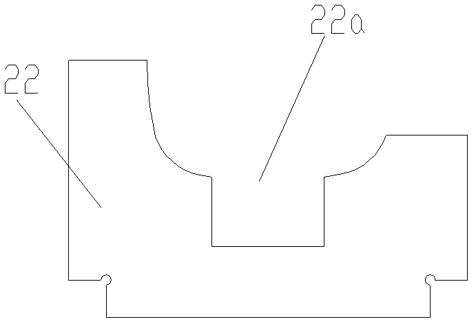
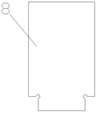
[0024] figure 1 It is a structural schematic diagram of the present invention, figure 2 The schematic diagram of the main pallet structure, image 3 It is a schematic diagram of the shell baffle structure, Figure 4 It is a schematic diagram of the structure of the exhaust pipe positioning plate, Figure 5 Schematic diagram of the positioning guide plate structure, Figure 6 It is a structural schematic diagram of the moving pin fixing plate, as shown in the figure: the welding mold of the muffler bracket of this embodiment includes a bottom plate 1, a muffler positioning component and a muffler bracket positioning component;

[0025] The muffler positioning assembly includes an exhaust pipe positioning assembly and a muffler housing positioning assembly; the muffler housing positioning assembly includes a housing baffle plate 8 and a main pallet 22 fixed on the floor, and the upper end of the main pallet 22 is provided with a Half-contains and supports the groove of the ...


PUM


Abstract

The invention discloses a silencer support frame welding mold, which comprises a bottom plate, a silencer positioning assembly and a silencer support frame positioning assembly, wherein the silencer positioning assembly comprises an exhaust pipe positioning assembly and a silencer casing positioning assembly, the silencer support frame positioning assembly comprises a positioning guide plate and a moving pin assembly, and a silencer support frame is aligned with a welding point of a silencer casing through being positioned behind a moving pin. The silencer support frame welding mold adopts a multi-point fast positioning structure and comprises the exhaust pipe positioning assembly, the silencer casing positioning assembly and the support frame positioning assembly, and in addition, the fast driven moving positioning structure is combined, so the welding positioning process is standardized, the form and position accuracy of the welding processing can be ensured, the work efficiency is improved, the additional stress after the installation of a silencer is reduced or even eliminated, the service life is prolonged, the work intensity of operators is reduced, and the production cost and use cost are saved.

Description

technical field [0001] The invention relates to a welding processing auxiliary device, in particular to a welding mold for a muffler bracket. Background technique [0002] Welding process is a way of combining and fixing different parts by welding. For the welding between small parts, the self-weight is light, and the positioning effect is not good, which is prone to deviation. Unlike other connection methods, welding is a non-detachable connection. If there is a large accuracy error, it will affect the quality of the entire product and even be scrapped. [0003] In the prior art, the welding between the various parts of the small muffler requires relatively precise precision standards to ensure that there is no interference between the various parts when the muffler is installed; especially in the process of welding the installation bracket of the muffler, it is generally necessary Based on the experience of the operator to ensure the shape and position error, generally t...

Claims


Application Information

Patent Timeline
Patent Type & Authority Applications(China)
IPC IPC(8): B23K37/04
Inventor 艾刚涂定国
Owner CHONGQING BEIBEI DISTRICT FENGHUO MACHINERY MFG
Why Eureka
Try Eureka