Fall detection device and passenger transporter

A technology for passenger conveyors and detection devices, which is used in transportation, packaging, escalators, etc., can solve problems such as wrong actions, inability to accurately find the center point, and being located outside the scanning area, and achieve the effect of detecting falls.

Active Publication Date: 2012-01-25
MITSUBISHI ELECTRIC CORP +1
View PDF5 Cites 3 Cited by
  • Summary
  • Abstract
  • Description
  • Claims
  • Application Information

AI Technical Summary

Problems solved by technology

[0006] In conventional safety devices for passenger conveyors, the center point is captured from the outline data (shape) of the detected object (user) captured by the laser scanning sensor, and the retention is measured based on the number of center points and the moving speed. and the overcrowded state, so when the user (passenger) falls, for example, even if the head is located near the entrance and exit, the foot is located outside the scanning area. In this state, the center point cannot be accurately calculated. There are cases where a fall cannot be detected
Also, even if the center point is calculated, the center is located outside the entrance and exit, so there may be cases where it is judged that there is no problem and the alarm is not sounded.
In addition, when the fallen user moves his hands and moves his hands and feet to make small movements, the center point is captured on the hand part, and the hand is moving moderately, and it is mistakenly recognized as a crowded state and judged as an appropriate passage. state, it is possible not to detect a fall
In addition, if the laser is projected far away, there is a possibility of erroneous operation due to retention far away from the passenger conveyor

Method used


Image

  • Fall detection device and passenger transporter
  • Fall detection device and passenger transporter
  • Fall detection device and passenger transporter

Examples


Embodiment 1

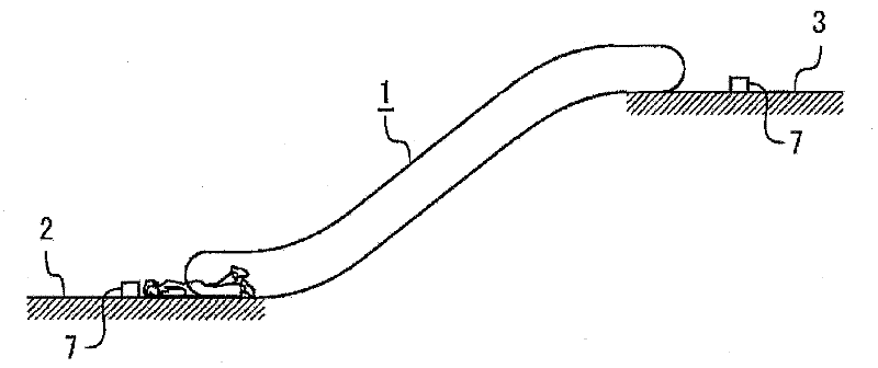
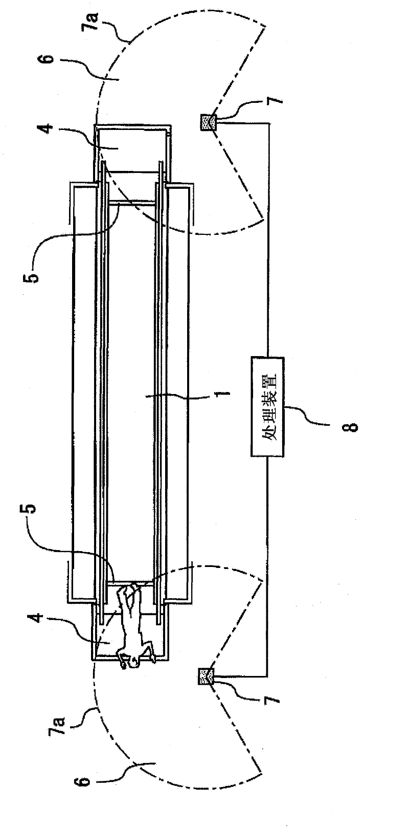
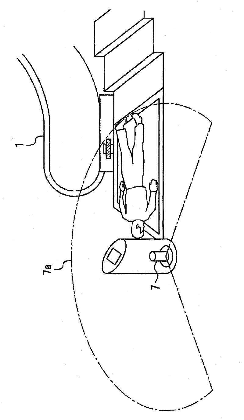
[0024] figure 1 It is a side view showing the general structure of the entire passenger conveyor provided with the fall detection device according to Embodiment 1 of the present invention, figure 2 is a plan view showing the fall detection device and the passenger conveyor, image 3 It is a perspective view showing a fall detection device and an entrance / exit portion of a passenger conveyor, Figure 4 It is an explanatory diagram showing the scanning range of the scanning distance sensor used in the fall detection device, Figure 5 It is an explanatory diagram showing the scanning range of the scanning distance sensor used in the fall detection device and the calculation concept for detecting falls, Image 6 It is an explanatory diagram showing the situation of analyzing the state of falling and staying by using the fall detection device, Figure 7 is a flowchart illustrating a fall detection algorithm of a fall detection device, Figure 8 It is a plan view of main parts ...


PUM


Abstract

A fall detection device and a passenger transporter, which can reliably detects the fall of a user (or a passenger). The fall detection device possesses scan type distance sensors (7); the scan type distance sensors (7) are arranged at each entrance and exist (2, 3) near the entrance and exist of a lower layer station. A laser beam is emitted horizontally in the scan area of a floor layer plate (4) and a passage (6) for accessing. The scan type distance sensors calculate the standard deviation of the data distance change with time of the data in the preset detection area according to the detected distance at each angle, and the standard deviation of the standard deviation is caculated. Under the condition that the standard deviation of the standard deviation is taken as the threshold, the surface dimension (which is the length) of the object in the area is caculated, and when the surface dimension (which is the length) of the object continuously exceeds the threshold, the state is determined to be a fall state.

Description

technical field [0001] The present invention relates to a fall detection device and passenger conveyors such as escalators and moving walks. Background technique [0002] In a passenger conveyor, when a user (passenger) gets off the running passenger conveyor at an entrance, there is a possibility of a mistake and a fall. If a user accidentally falls at an entrance or exit, the fall of the user cannot be detected normally, and it is desired to improve this situation. [0003] A safety device for a passenger conveyor has been proposed in the past (for example, refer to Patent Document 1). The movement of the user on the plane coordinates, when the moving speed of the user measured by the laser scanning sensor (the information on the staying state of the entrance and exit department) is lower than a predetermined value, the speech synthesis device is used to make a reminder broadcast, and at the same time the user is staying Or when it is crowded for a long time, control the...

Claims


Application Information

Patent Timeline
Patent Type & Authority Applications(China)
IPC IPC(8): B66B29/00B66B25/00B66B21/02
Inventor 猪又宪治平井敬秀鹿井正博茑田广幸伊藤宽
Owner MITSUBISHI ELECTRIC CORP
Why Eureka
Try Eureka