Supercharge Your Innovation With Domain-Expert AI Agents!

Electromagnetic actuating device

An adjustment device, electromagnetic technology, applied in the direction of valve devices, circuits, magnets, etc.

Inactive Publication Date: 2013-11-27
SCHAEFFLER TECH AG & CO KG
View PDF9 Cites 0 Cited by
  • Summary
  • Abstract
  • Description
  • Claims
  • Application Information

AI Technical Summary

Problems solved by technology

[0008] In addition to a common housing, all the mentioned adjustment devices with several actuator pins require considerable production and assembly expenditure, since the optimum combination of production costs is primarily achieved only by means of a common housing

Method used


Image

  • Electromagnetic actuating device

Examples


Embodiment Construction

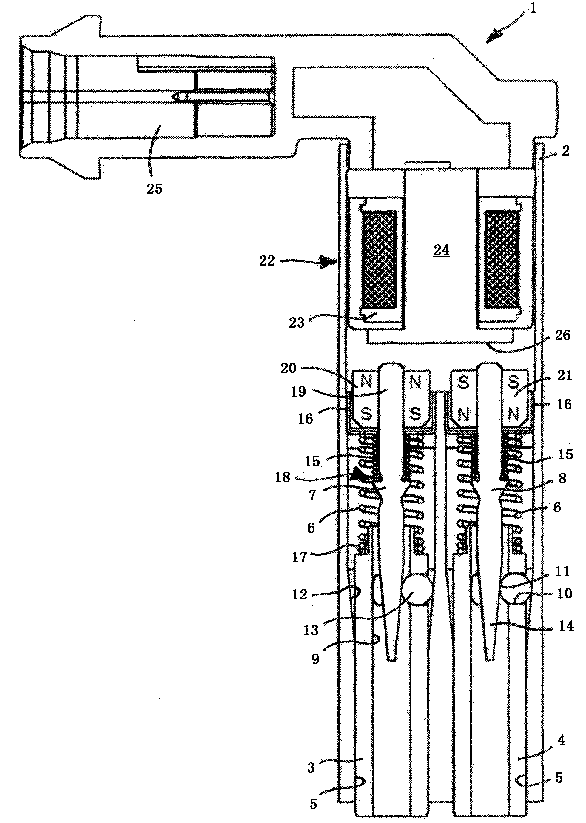
[0025] The drawing discloses an adjusting device 1 for controlling the variable-stroke valve train described at the outset with displaceable cam elements (cf. DE 196 11 641 C1). The adjusting device is a structural unit that can be installed in a cylinder head of an internal combustion engine and has a housing 2 and two hollow-cylindrical actuator pins 3 and 4 arranged in the housing 2 . The actuator pins 3 , 4 configured as identical parts are supported in the longitudinal guide 5 of the housing 2 and can be moved independently of one another in the rest position (as shown) into the housing 2 and out of the housing 2 . 2. Move back and forth between the working positions driven out in 2. As already explained above, the actuator pins 3 , 4 engage in associated displacement grooves in the (not shown) operating position for displacing the cam element.

[0026] The actuator pins 3 , 4 , which are loaded by a spring mechanism (here helical compression spring 6 ) in the direction...


PUM


Abstract

An electromagnetic actuating device (1) having a housing (2) and two actuator pins (3, 4) that are supported in the housing so as to be movable independently of each other between a retracted rest position and an extended working position, and locking pins (7, 8) that hold the actuator pins in the rest position via locking mechanisms and that can be moved relative to the actuator pins in the movement direction of the actuator pins. A force is applied to the locking pins in the extension direction by further spring elements (15), and the locking pins are moved in the retraction direction by electromagnetic force application in order to unlock the locking mechanisms. The actuating device is an electromagnet (22) associated with the locking pins in common and having a reversible direction of the magnetic field, and the end sections (19) of the locking pins facing away from the actuator pins are provided with bipolar permanent magnets (20, 21) that are oriented with opposite polarities in the movement direction.

Description

technical field [0001] The invention relates to an electromagnetic adjustment device with a housing; The working positions where the housing moves out are supported in the housing in such a way that they move independently of each other, and are loaded by a spring mechanism in the direction of moving out; The actuator pin remains in a rest position and is movable relative to the actuator pin in the direction of travel of the actuator pin. In this case, the blocking pin is biased by a further spring mechanism in the direction of retraction and is electromagnetically biased in the direction of retraction in order to release the catch. Background technique [0002] Such an adjusting device is particularly suitable for adjusting a variable-stroke valve train of an internal combustion engine, the basic operating principle of which is disclosed, for example, in DE 10 2004 021 376 A1. The stroke variability of the valve train is based on a cam element having two cams arranged dir...

Claims


Application Information

Patent Timeline
Patent Type & Authority Patents(China)
IPC IPC(8): F01L1/047
CPCF01L1/047H01F7/1646F01L2820/031F01L2013/0052H01F7/122F01L13/0036
Inventor 安德烈亚斯·内德尔
Owner SCHAEFFLER TECH AG & CO KG
Features
  • R&D
  • Intellectual Property
  • Life Sciences
  • Materials
  • Tech Scout
  • Unparalleled Data Quality
  • Higher Quality Content
  • 60% Fewer Hallucinations
Learn More