
Electric-part clicking mechanism

A technology of electrical components and locking, applied in the direction of electrical components, circuits, electric switches, etc., can solve the problems that hinder the miniaturization of electrical components, durability problems, shell wear, etc., and achieve a clear sense of locking, good durability, The effect of reducing wear

Active Publication Date: 2014-08-27
TOKYO COSMOS ELECTRIC CO LTD
View PDF7 Cites 0 Cited by
  • Summary
  • Abstract
  • Description
  • Claims
  • Application Information

AI Technical Summary

Problems solved by technology

[0007] However, as in the above-mentioned conventional example, the balls are in elastic contact with the concavities and convexities formed in a row on the other side of the housing. In such a structure, the balls make point contact (point abutment) and cause local wear of the housing. Therefore, in terms of durability, There is a problem
[0008] In addition, in an electrical component such as a switch whose operation shaft is rotated, for example, it is necessary to generate a strong torque (step torque) in order to obtain a clear locking feeling, but in order to generate a strong torque Therefore, it is necessary to use a coil spring with a thick wire diameter, which hinders the miniaturization of electrical components corresponding to the increase in the outer diameter of the coil spring.

Method used


Image

  • Electric-part clicking mechanism
  • Electric-part clicking mechanism
  • Electric-part clicking mechanism

Examples


Embodiment Construction

[0026] Hereinafter, examples of the present invention will be described.

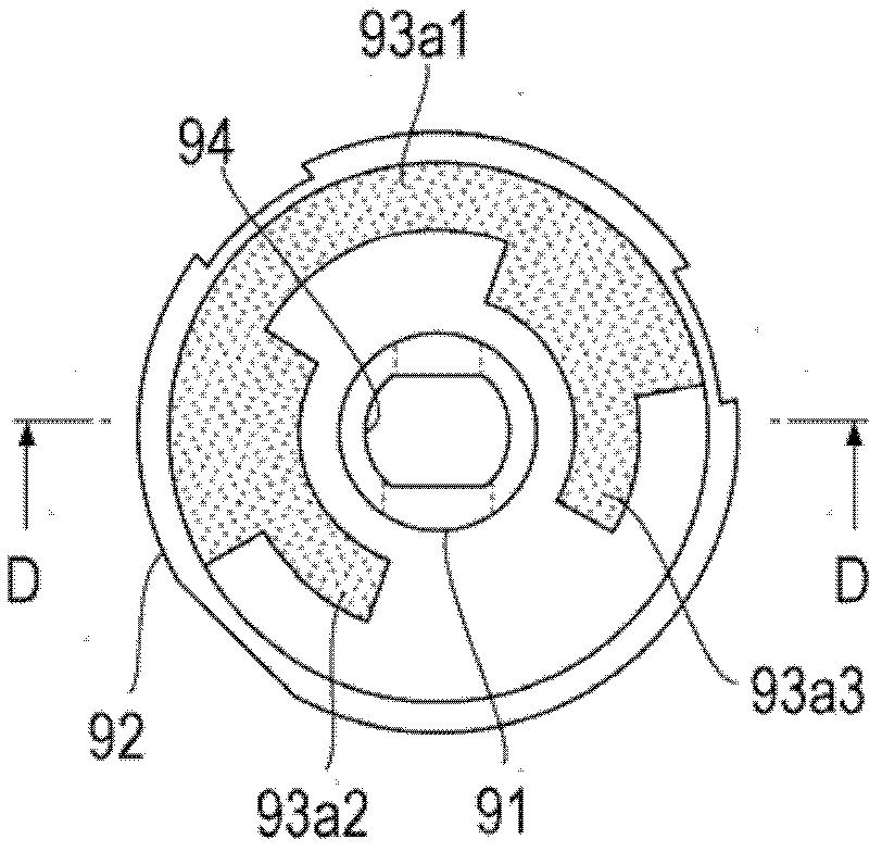
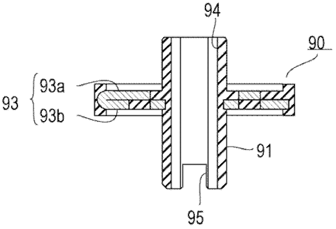
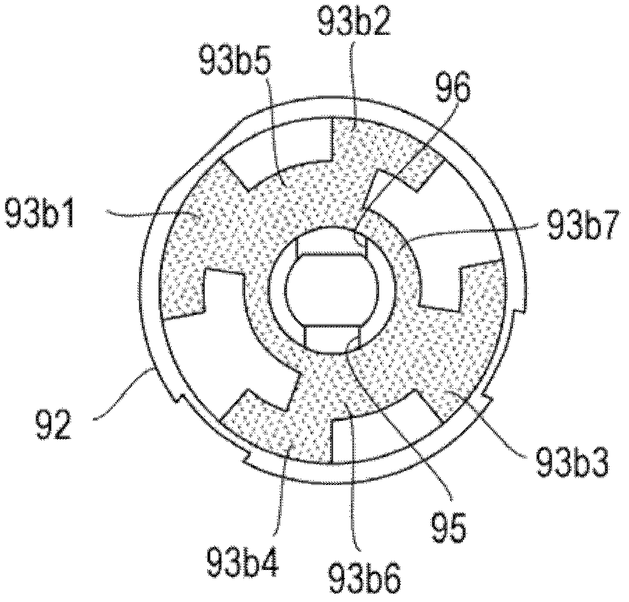
[0027] figure 2 As an example of an electrical component including the locking mechanism of the present invention, each part showing the configuration of a rotary switch is disassembled. The switch is composed of the following components: rotating operation shaft 10, bearing 20, ring 30, rotating plate 40, spring 50, locking stopper 60, middle plate 70, lower side contact bracket 80 for holding the contact, rotating body 90, and for holding the contact. The upper contact bracket 100 , the cover 110 and the rivet 120 .

[0028] The rotary operation shaft 10 includes: an operation part 11, a holding part 12 extending coaxially from the front end of the operation part 11 and having a smaller diameter than the operation part 11, and a holding part 12 coaxially extending from the front end of the holding part 12 and having a smaller diameter than the holding part 12 drive unit 13. An annular groove 12 a ...


PUM


Abstract

The invention provides a locking mechanism for electrical components. The locking mechanism has: a spring (50) disposed on a rotating plate (40) that rotates integrally with a rotating operation shaft of an electrical component and formed of a plate; Concave-convex (25), which is arranged on the inner peripheral surface of the casing (22) that accommodates the rotating plate (40), is formed along its circumferential direction. The locking stopper (60) has a cylindrical shape, and the peripheral surface part of the locking stopper (60) is elastically contacted with the unevenness (25) by the force of the spring (50). Accordingly, it is possible to realize a locking mechanism of an electric component that can provide a good and clear locking feeling, has high durability, and can be downsized.

Description

technical field [0001] The present invention relates to a locking mechanism for generating a locking feeling (a sense of jerk) when operating an electrical component that is rotated or slid. Background technique [0002] As a conventional locking mechanism of this type, for example, as described in Patent Document 1 or Patent Document 2, there is a locking mechanism using a ball and a coil spring. [0003] figure 1 It shows the structure around the switch box and the movable plate of the rotary switch equipped with the locking mechanism disclosed in Patent Document 1. figure 1 Among them, reference numeral 1 denotes a switch box, 2 denotes an operation shaft for rotating operation, and 3 denotes a movable plate fixed to the operation shaft 2 . In addition, reference numeral 4 denotes a movable contact that is in contact with a fixed contact (not shown), and 5 denotes a coil spring that urges the movable contact 4 toward the fixed contact and urges the movable plate 3 Appl...

Claims


Application Information

Patent Timeline
Patent Type & Authority Patents(China)
IPC IPC(8): H01H15/16H01H19/11H01H19/56H01H19/58
CPCH01H19/14H01H19/11H01H15/16H01H19/56H01H19/58
Inventor 福岛肇福永太郎
Owner TOKYO COSMOS ELECTRIC CO LTD
Learn More