Thermal forming machine

A thermoforming machine and frame technology, applied in the field of thermoforming machines, can solve problems such as the inability to change the height of the closed mold, pollute the internal environment of the workshop, and increase the labor intensity of operators to clean the workshop.

Active Publication Date: 2012-02-01
GUANGDONG DESIGNER MASCH CO LTD
View PDF4 Cites 4 Cited by
  • Summary
  • Abstract
  • Description
  • Claims
  • Application Information

AI Technical Summary

Problems solved by technology

Since the fixed mold table is fixedly installed on the guide column, when the movable mold table lifting drive mechanism drives the movable mold table and the fixed mold table to close the mold and cut, the height of the closed mold cannot be changed. When the mold or shear is overloaded, it will often cause damage to the mold table, mold or movable mold table lifting drive mechanism
In addition, when the thermoforming machine starts to operate, because the temperature and other parameters have not been adjusted to the ideal state, the molded products at this time often do not meet the requirements. However, the thermoforming machine still cuts and discharges the molded products that do not meet the requirements, polluting the workshop The internal environment increases the labor intensity of operators to clean up the workshop

Method used


Image

  • Thermal forming machine
  • Thermal forming machine
  • Thermal forming machine

Examples


Embodiment Construction

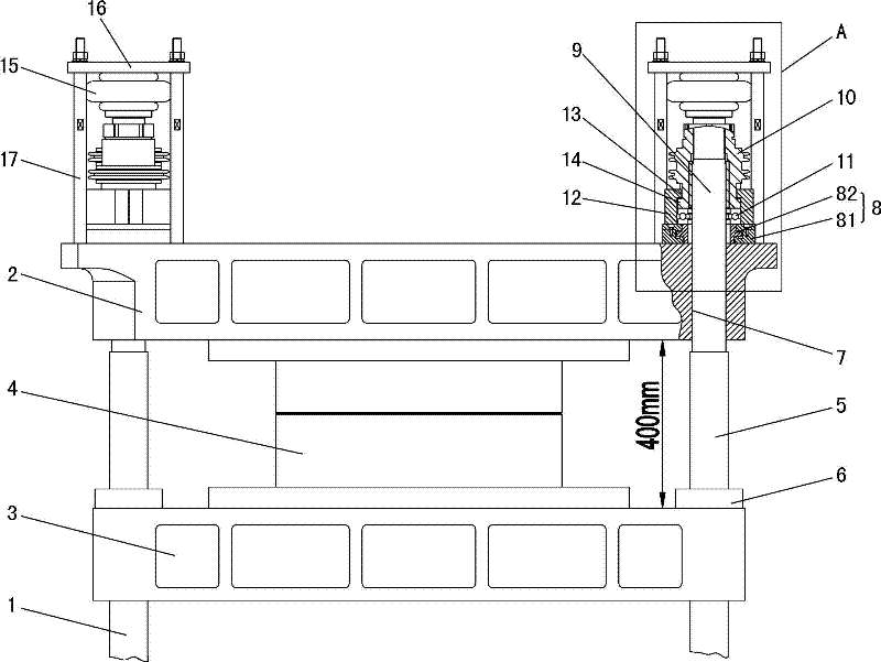
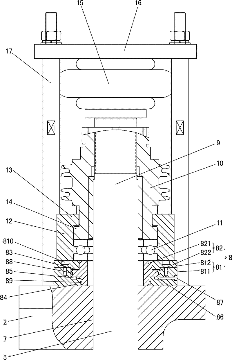
[0026] Such as Figure 1 to Figure 4 As shown, this thermoforming machine includes a frame 1, a fixed mold table 2, a movable mold table 3, a lifting drive mechanism for the movable mold table (the lifting drive mechanism for the movable mold table can use an existing mechanism, and will not be described in detail here) and a fixed mold table. Die table position adjustment mechanism.

[0027] Die 4 is installed on the fixed mold platform 2, the movable mold platform 3, the movable mold platform lifting drive mechanism is a cam mechanism (or connecting rod mechanism), and the movable mold platform 3 is connected with the power output end of the movable mold platform lifting drive mechanism.

[0028] The frame 1 includes four guide posts 5 going up and down; the movable mold table 3 is provided with four first guide sleeves 6, and the first guide sleeves 6 are matched with the guide posts 5 one by one, and the guide posts 5 are in the first guide posts. In the cover 6; the fixe...


PUM


Abstract

The invention discloses a thermal forming machine comprising a frame, a fixed mold platform, a mobile mold platform, and a mobile mold platform elevation driving mechanism. Molds are arranged on the fixed mold platform and the mobile mold platform. The mobile mold platform elevation driving mechanism is a cam mechanism or a linkage mechanism. The mobile mold platform is connected to a power output terminal of the mobile mold platform elevation driving mechanism. The machine is characterized in that: the thermal forming machine also comprises a fixed mold platform position adjusting mechanism;and the fixed mold platform position adjusting mechanism comprises at least one fixed mold platform position adjusting hydraulic cylinder used for applying thrusting forces upon the fixed mold platform towards the mobile mold platform. According to the invention, the fixed mold platform position adjusting hydraulic cylinder is arranged in the thermal forming machine, and certain thrusting forces can be applied on the fixed mold platform towards the mobile mold platform by the fixed mold platform position adjusting hydraulic cylinder. When mold platform closing or shearing overloading is caused by an unexpected event, a designed output pressure of the fixed mold platform position adjusting hydraulic cylinder is exceeded, and the fixed mold platform position adjusting hydraulic cylinder is forced to flyback, such that the mold platforms, the molds and the mobile mold platform elevation driving mechanism are prevented from being damaged. Therefore, a self-protection function is provided for the machine.

Description

technical field [0001] The invention relates to a thermoforming machine. Background technique [0002] Thermoforming machines are usually used to make and process plastic materials into various plastic products. [0003] Thermoforming machines generally include a frame, a fixed mold table, a movable mold table, and a lifting drive mechanism for the movable mold table; molds are installed on the fixed mold table and the movable mold table; the lifting drive mechanism for the movable mold table usually adopts a cam mechanism or a connecting rod mechanism, Among them, the cam mechanism is more common; the movable mold table is connected with the power output end of the movable mold table lifting drive mechanism. Usually the fixed mold table is set above the movable mold table (the fixed mold table can also be set under the movable mold table), and the fixed mold table can be fixedly installed on the frame. In order to make the movable mold table rise and fall smoothly, the ab...

Claims


Application Information

Patent Timeline
Patent Type & Authority Applications(China)
IPC IPC(8): B29C51/18B29C51/26
Inventor 罗庆青章俊波
Owner GUANGDONG DESIGNER MASCH CO LTD
Why Eureka
Try Eureka