
Vacuum moving device and method

A technology of vacuum movement and vacuum chamber, which is applied in the field of vacuum movement and vacuum movement devices, can solve the problems of high cost, limited movement mode, complex design, etc., and achieve the effect of low driving cost, reduced implementation cost and simple design

Active Publication Date: 2012-02-01
KINGSTONE SEMICONDUCTOR LIMITED COMPANY
View PDF4 Cites 4 Cited by
  • Summary
  • Abstract
  • Description
  • Claims
  • Application Information

AI Technical Summary

Problems solved by technology

[0004] The technical problem to be solved by the present invention is to overcome the defects of complex design, high cost and limited movement modes of the vacuum moving device in the prior art, and provide a simple, reliable and flexible vacuum moving device that can realize moving objects in vacuum. Vacuum moving device for complex movement and corresponding vacuum moving method

Method used


Image

  • Vacuum moving device and method
  • Vacuum moving device and method
  • Vacuum moving device and method

Examples


Embodiment 1

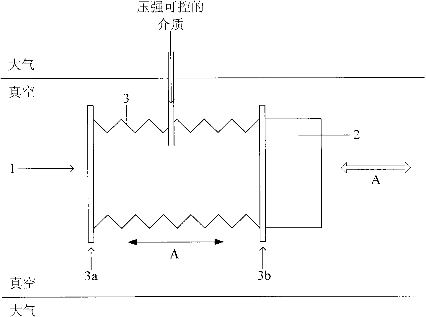
[0027] Such as figure 2 As shown, in this embodiment, a bellows 3 is used to realize the translation of the moving object 2 . By adjusting the pressure of the medium in the bellows 3, the bellows 3 reciprocates and expands in the direction shown by the arrow A, and the fixed end 3a of the bellows 3 is fixed, so the bellows 3 The moving end 3b of the moving object 2 will drive the moving object 2 to move back and forth along the direction indicated by the arrow A.

Embodiment 2

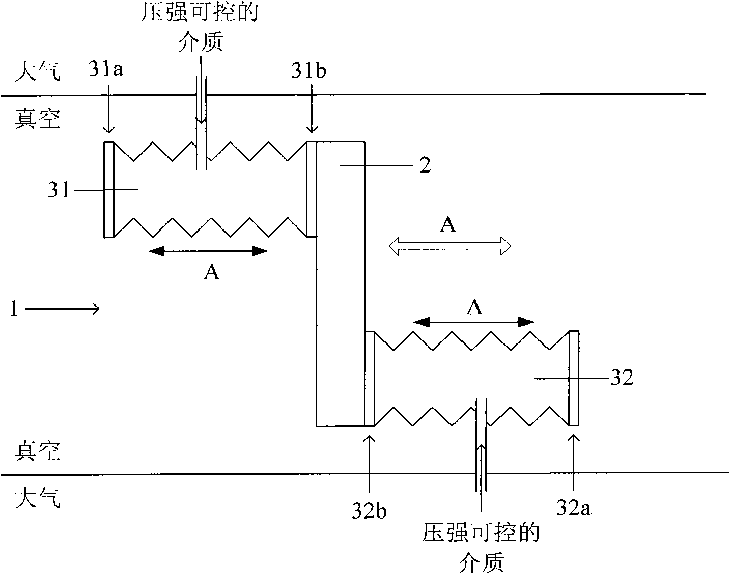
[0029] Such as image 3 As shown, in this embodiment, two bellows 31 , 32 are used to realize the translation of the moving object 2 . By adjusting the pressure of the medium inside the two bellows 31, 32, the bellows 31 shrinks along the direction shown by the arrow A, while the bellows 32 elongates along the direction shown by the arrow A, or The corrugated tube 31 is elongated along the direction shown by arrow A, while the corrugated tube 32 is shrunk along the direction shown by arrow A, and the fixed ends 31a, 32a of the corrugated tubes 31, 32 are fixed. , so the moving ends 31b, 32b of the two bellows 31, 32 will drive the moving object 2 to reciprocate along the direction indicated by the arrow A.

[0030] The method of realizing the translation of the moving object 2 by using multiple bellows is completely the same as the realization principle of this embodiment, so it will not be repeated here.

Embodiment 3

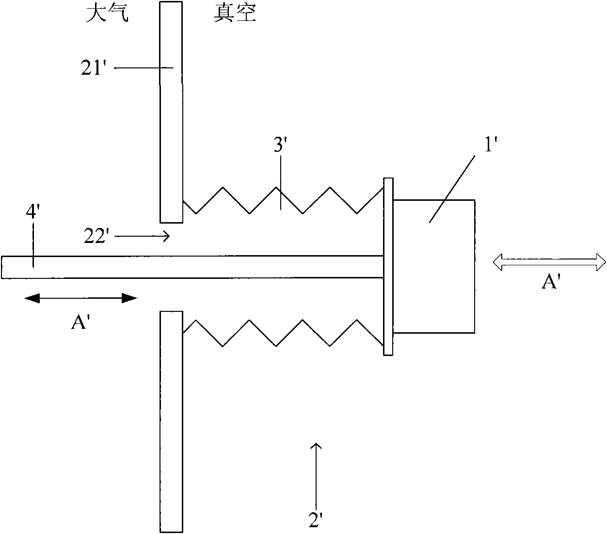
[0032] Such as Figure 4 As shown, in this embodiment, a bellows 3 is used to realize the rotation of the moving object 2, wherein the rotation axis O of the moving object 2 is perpendicular to the paper surface, and the expansion and contraction direction of the bellows 3 does not pass through the rotation Axis O. By adjusting the pressure of the medium in the bellows 3, the bellows 3 reciprocates and expands in the direction shown by the arrow A, and the fixed end 3a of the bellows 3 is fixed, so the bellows 3 The moving end 3b of the moving object 2 will drive the moving object 2 to reciprocate and rotate around the rotation axis O along the direction indicated by the arrow B.


PUM


Abstract

The invention discloses a vacuum moving device, which is used for moving a mobile object in a vacuum cavity and comprises at least one corrugated pipe. The corrugated pipes are arranged in the vacuum cavity, the two ends of each corrugated pipe are closed, one end of each corrugated pipe is fixedly arranged in the vacuum cavity, the other end of each corrugated pipe is connected with the mobile object, each corrugated pipe is filled with a medium and is communicated with a medium source arranged outside the vacuum cavity through a pipeline, and the medium source is used for controlling each corrugated pipe to flex via independently controlling the medium pressure in each corrugated pipe. The invention also discloses a vacuum movement method using the vacuum moving device. The vacuum moving device and the method have a simple, practical and reliable design, the design difficulties and the implementation cost of the vacuum moving device can be greatly reduced. Moreover, more flexible and complex movement of the mobile object can be achieved conveniently.

Description

technical field [0001] The invention relates to a mechanical moving device in vacuum, in particular to a vacuum moving device and a corresponding vacuum moving method. Background technique [0002] In order to make a moving object in a vacuum environment, such as a workpiece support in a vacuum chamber, move according to the process requirements, the structure of the vacuum moving device commonly used at present is as follows: figure 1 As shown, wherein a moving object 1' is located in a vacuum chamber 2', in order to realize the controllable movement of the moving object 1', an opening 22' is provided on a side wall 21' of the vacuum chamber 2', and a One closed end of the bellows 3' is connected to the moving object 1', while the other open end is hermetically arranged around the periphery of the opening 22', and the vacuum chamber 2' is realized by using the bellows 3'. The isolation between the vacuum environment and the atmospheric environment. In addition, a transmiss...

Claims


Application Information

Patent Timeline
IPC IPC(8): C23C14/56C23C14/00C23C16/54C23C16/00
Inventor 陈炯
Owner KINGSTONE SEMICONDUCTOR LIMITED COMPANY
Learn More