
Two-layer manual liner anti-seepage structure for storage tank foundation and construction method for two-layer manual liner anti-seepage structure

A storage tank foundation and artificial technology, applied in infrastructure engineering, protective devices, buildings, etc., can solve the problems of limited discharge capacity of oil-water mixture, economic loss, easy fire, etc., to avoid environmental pollution and economic loss, increase The effect of a large safety factor

Active Publication Date: 2012-02-01
BC P INC CHINA NAT PETROLEUM CORP +1
View PDF4 Cites 8 Cited by
  • Summary
  • Abstract
  • Description
  • Claims
  • Application Information

AI Technical Summary

Problems solved by technology

In the past, in the oil and gas storage and operation industry, the leakage of oil tanks was mainly judged by observing whether there were abnormal oil stains or strong oil smells in the ground, drainage ditches and pipe trenches in the tank area. The anti-seepage structure layer or only a single layer of anti-seepage structure layer, once the anti-seepage structure layer is accidentally damaged, it cannot effectively prevent the leakage of oil products, and cannot completely eliminate the leakage
Moreover, in the current technology, oil seepage holes are only provided on the ring beam of the tank foundation without diversion, and the ability to discharge the leaked oil-water mixture in time is limited, which not only causes economic losses and environmental pollution, but also easily causes fires and explosions ACCIDENT

Method used


Image

  • Two-layer manual liner anti-seepage structure for storage tank foundation and construction method for two-layer manual liner anti-seepage structure
  • Two-layer manual liner anti-seepage structure for storage tank foundation and construction method for two-layer manual liner anti-seepage structure

Examples


Embodiment 1

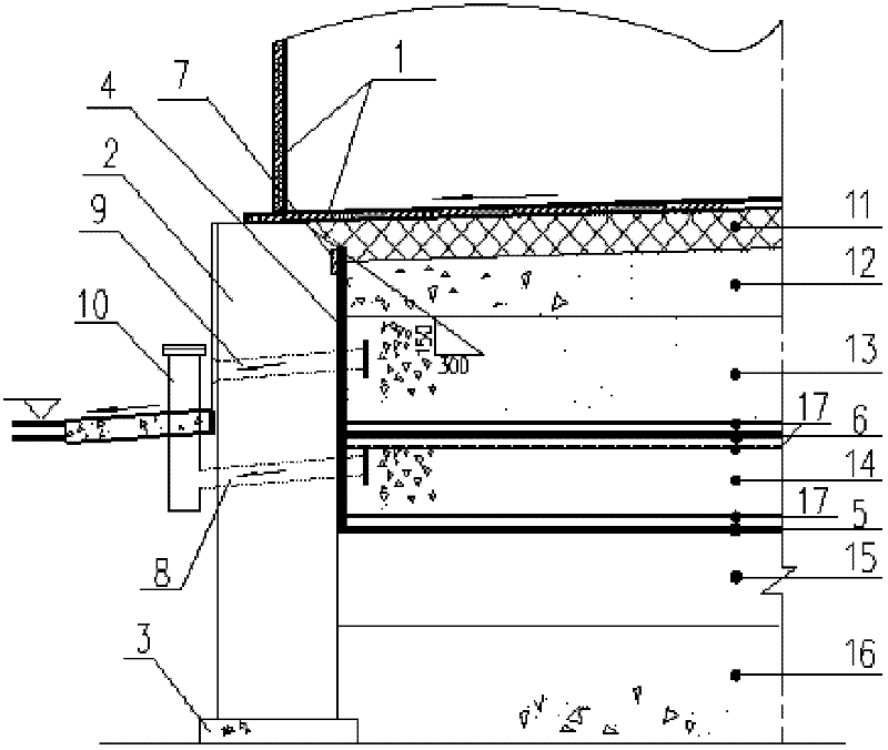
[0024] Embodiment 1: Taking the construction method of a double-layer artificial lining anti-seepage structure of a storage tank foundation as an example, the present invention is further described in detail.

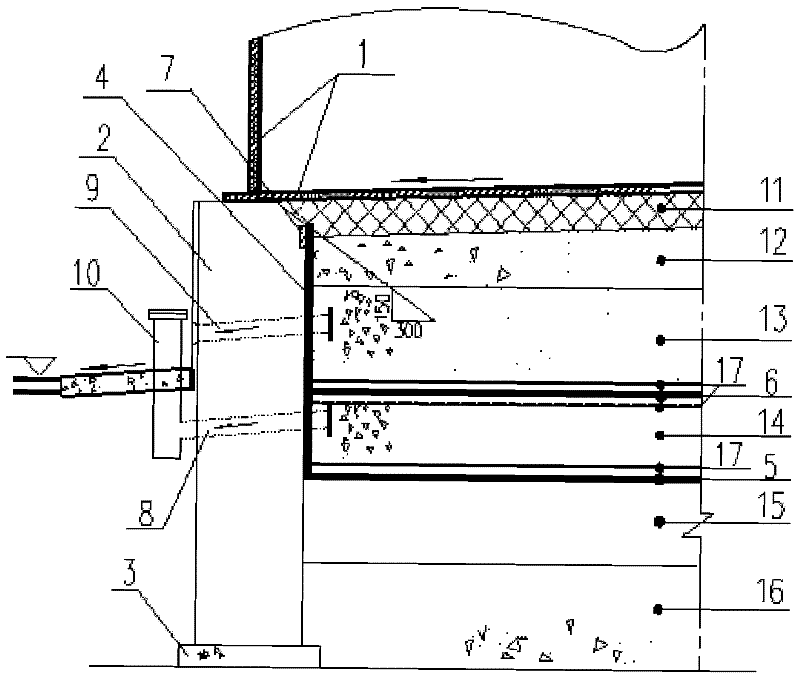
[0025] refer to figure 1 . A double-layer artificial lining anti-seepage structure for a storage tank foundation, including a circular ring beam, a ring beam foundation cushion, and an inner cushion of the ring beam; and an anti-seepage membrane embedded in the storage tank ring beam 2 In the internal pad, the anti-seepage membrane includes a vertical anti-seepage membrane 4, a first layer of horizontal anti-seepage membrane 5 and a second layer of horizontal anti-seepage membrane 6, the vertical anti-seepage membrane 4, the first layer of horizontal anti-seepage Membrane 5 and the second layer of horizontal anti-seepage membrane 6 are connected as a whole, vertical anti-seepage membrane 4 runs along the inner surface of the upper part of ring beam 2 to the top of ring...


PUM

PropertyMeasurementUnit
Thicknessaaaaaaaaaa
Thicknessaaaaaaaaaa
Thicknessaaaaaaaaaa

Abstract

The invention discloses a two-layer manual liner anti-seepage structure for a storage tank foundation, and applied to storage tank foundation seepage prevention. An anti-seepage film is embedded in a cushion layer in a ring beam of a storage tank, and comprises a vertical anti-seepage film and a horizontal anti-seepage film, which are connected into a whole; the vertical anti-seepage film is rolled up along the periphery of the surface of the ring beam to the top of the ring beam, and is fixed with the ring beam through an anti-seepage film embedded part; a first-layer horizontal anti-seepage film is provided with a first leakage detecting horizontal tube; a second leakage detecting horizontal tube is arranged between the first-layer horizontal anti-seepage film and the second-layer horizontal anti-seepage film, and a leakage detecting vertical tube is communicated with the two leakage detecting horizontal tubes; and a filtrate layer is positioned on the first-layer horizontal anti-seepage film and the second-layer horizontal anti-seepage film respectively. The invention has the advantages that: two-layer anti-seepage and leakage detecting measures are taken in the structure of the tank foundation, the anti-seepage and leakage detecting safety coefficient is increased, an oil leakage phenomenon can be effectively monitored, remedial measures are convenient to take, and leaked oil can be prevented from further infiltrating soil.

Description

technical field [0001] The invention relates to the technical field of foundation anti-seepage treatment in the field of civil engineering, in particular to an anti-seepage structure of a storage tank foundation and a construction method thereof. Background technique [0002] Oil storage tanks are important equipment for storing oil products, and play a strategic role in national economic development, transportation, military and other fields. However, due to the influence of factors such as the engineering environment and working conditions where the oil tank is located, oil leakage often occurs on the bottom plate of the tank. The leaked oil-water mixture has a strong corrosion ability. Once it penetrates into the soil of the tank farm, it will cause serious pollution to the environment, resulting in serious engineering accidents and economic losses. Therefore, under the requirements of safety and environmental protection, it is of great significance to do a good job in t...

Claims


Application Information

Patent Timeline
IPC IPC(8): E02D31/00E02D27/38
Inventor 孙应桃岳忠郭宝申杜清华王育军高宏义李兵兵
Owner BC P INC CHINA NAT PETROLEUM CORP
Learn More