Vehicle oil level sensor and implementation method thereof
A technology of oil level sensor and implementation method, which is applied in the direction of buoy liquid level indicator, etc., which can solve the problems of low oil volume and difficult measurement, achieve accurate calculation results, and eliminate the effect of contact resistance interference
- Summary
- Abstract
- Description
- Claims
- Application Information
AI Technical Summary
Problems solved by technology
Method used
Image

Examples
Embodiment Construction
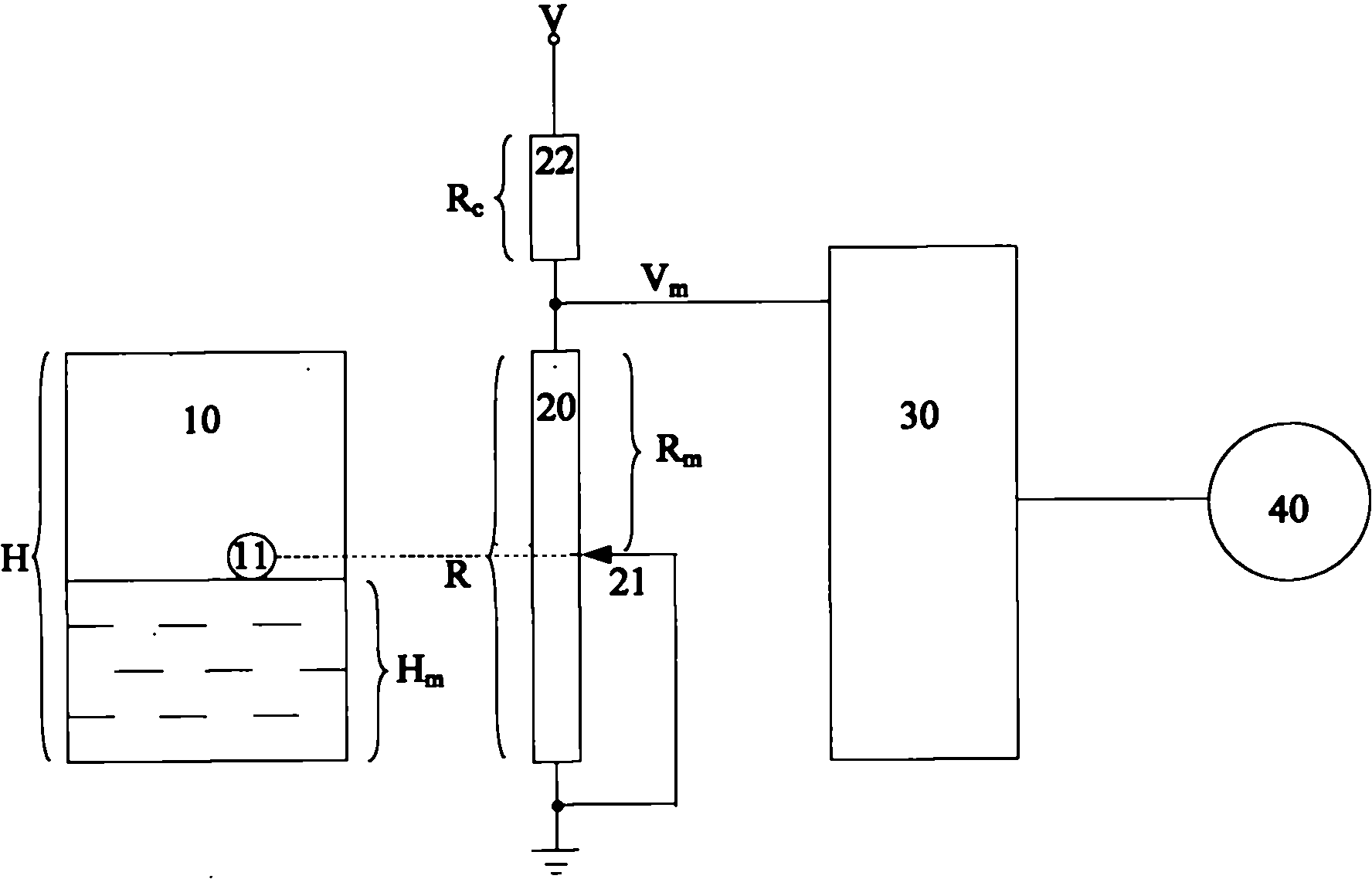
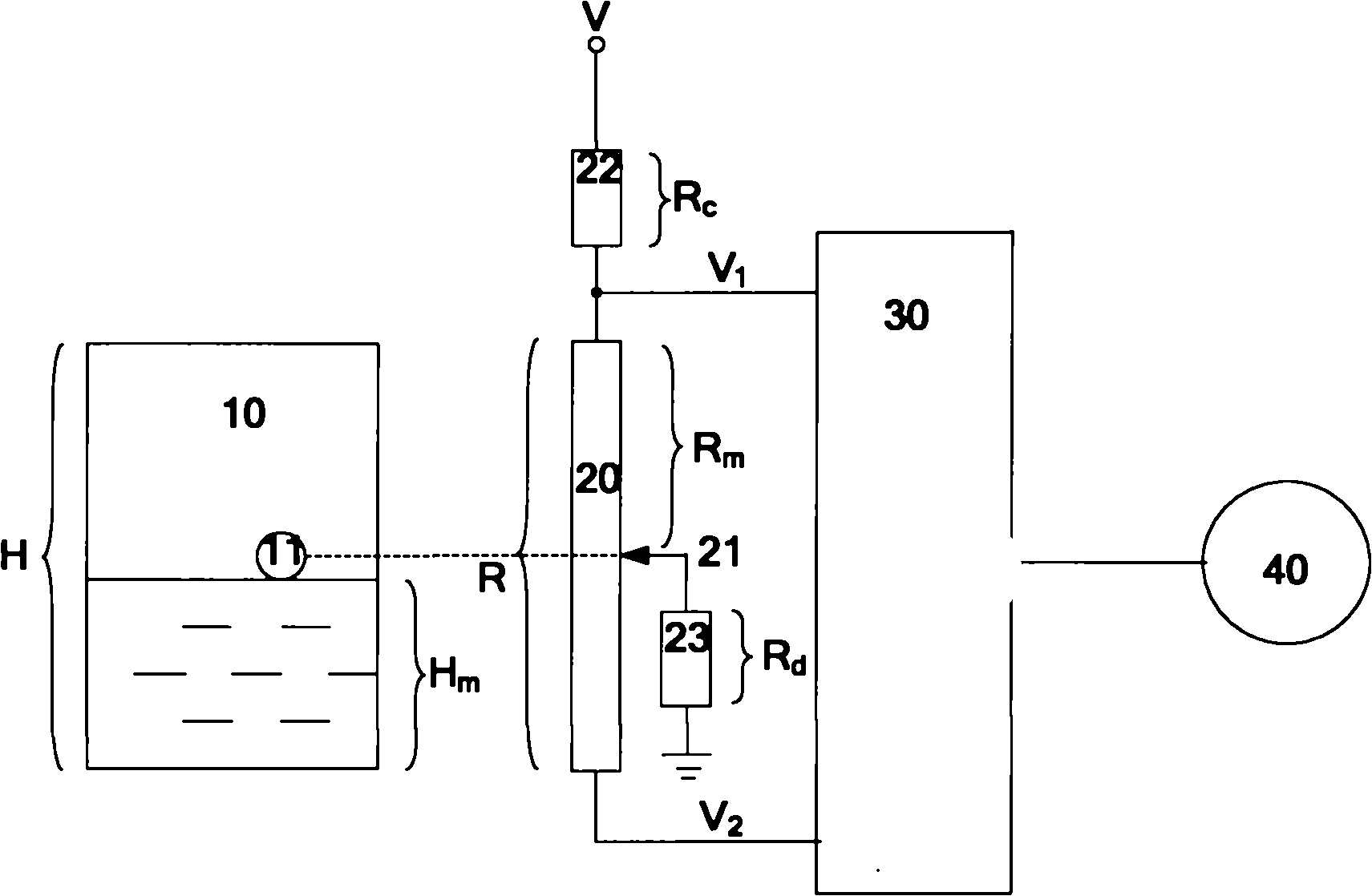
[0049] see image 3 , The vehicle fuel level sensor of the present invention includes a fuel tank 10 , a sliding rheostat 20 , a resistor one 22 , a resistor two 23 , an ECU30 and an instrument 40 . Wherein, the fuel tank 10 has a float 11 floating on the fuel surface, and the float 11 controls the position of the slide 21 on the sliding rheostat 20 . One end of the sliding rheostat 20 is connected in series with a resistor 1 22 and connected to the power supply V through the resistor 1 22 . The slide 21 on the sliding rheostat 20 is connected in parallel with a resistor 2 23 and grounded through the resistor 2 23 . The total resistance of the sliding rheostat 20 is R, and the effective resistance obtained by the sliding plate 21 is R m , the resistance of resistor one 22 is R c , the resistance of resistor 223 is R d . One end of the sliding rheostat 20 connected in series with the resistance one 22 is connected to the ECU30 and outputs a voltage V to the ECU30. 1 , the ...
PUM
 Abstract
Description
Claims
Application Information