Eureka AIR delivers breakthrough ideas for toughest innovation challenges, trusted by R&D personnel around the world.

Power generation device of vehicle

A technology for power generation devices and vehicles, applied in the direction of electromechanical devices, electrical components, electric components, etc., can solve problems affecting the strength of drive shafts, fuel consumption, etc.

Inactive Publication Date: 2012-02-01
KYMCO
View PDF7 Cites 5 Cited by
  • Summary
  • Abstract
  • Description
  • Claims
  • Application Information

AI Technical Summary

Problems solved by technology

[0004] Although it can achieve the effect of switching to drive the vehicle to move or to drive the generator to generate electricity, because the generator and the crankshaft of the internal combustion engine are coaxially arranged, it not only causes the width of the vehicle to be wider, but also affects the power of the vehicle. The strength of the crankshaft or the drive shaft of the generator, and the vehicle with the generator driven by the internal combustion engine can generate electricity at idle speed. Because the idle speed is low, it is more expensive to generate electricity at idle speed. Oil

Method used


Image

  • Power generation device of vehicle
  • Power generation device of vehicle
  • Power generation device of vehicle

Examples


Embodiment Construction

[0014] The aforementioned and other technical contents, features and effects of the present invention will be clearly presented in the following detailed description of a preferred embodiment with reference to the accompanying drawings.

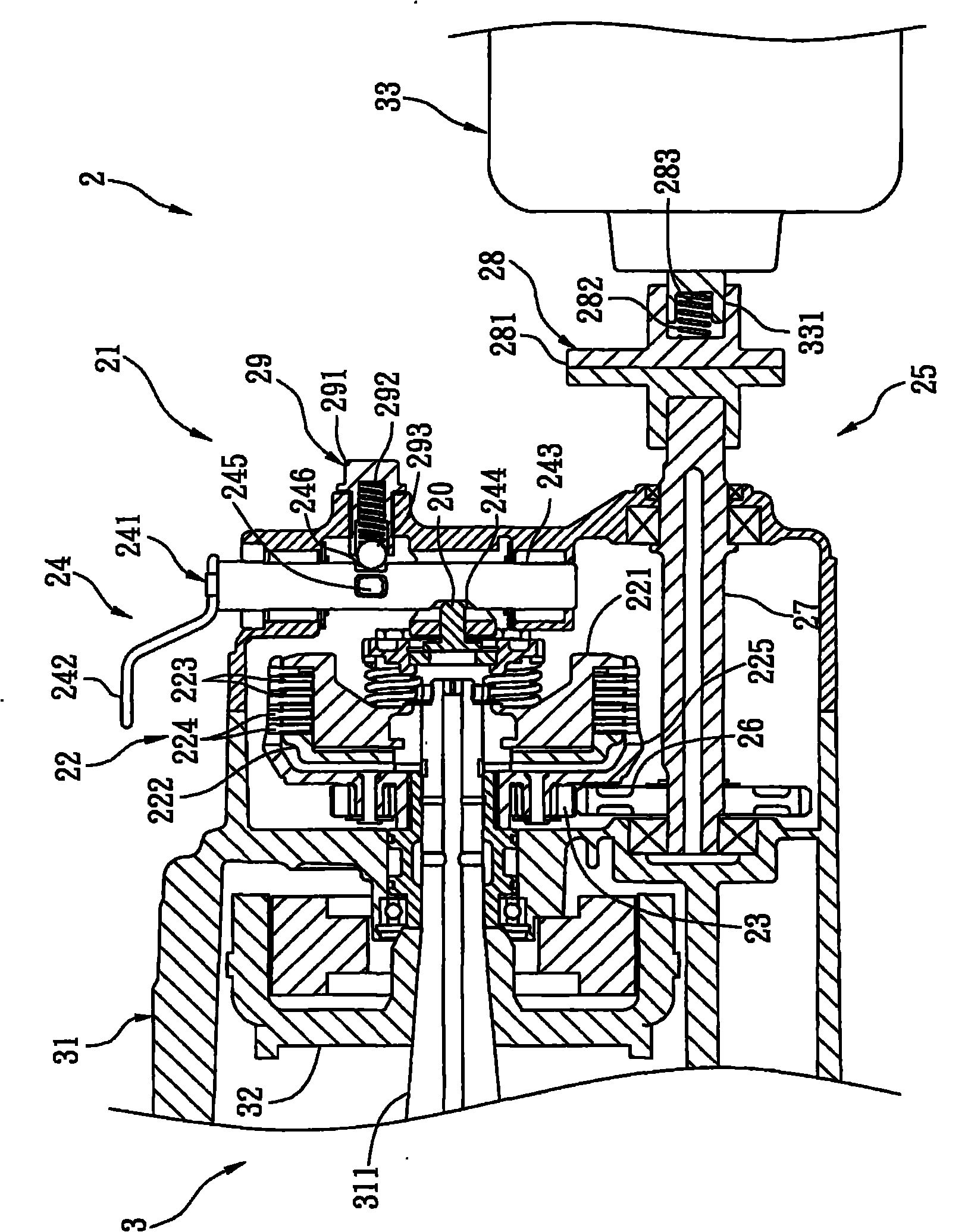
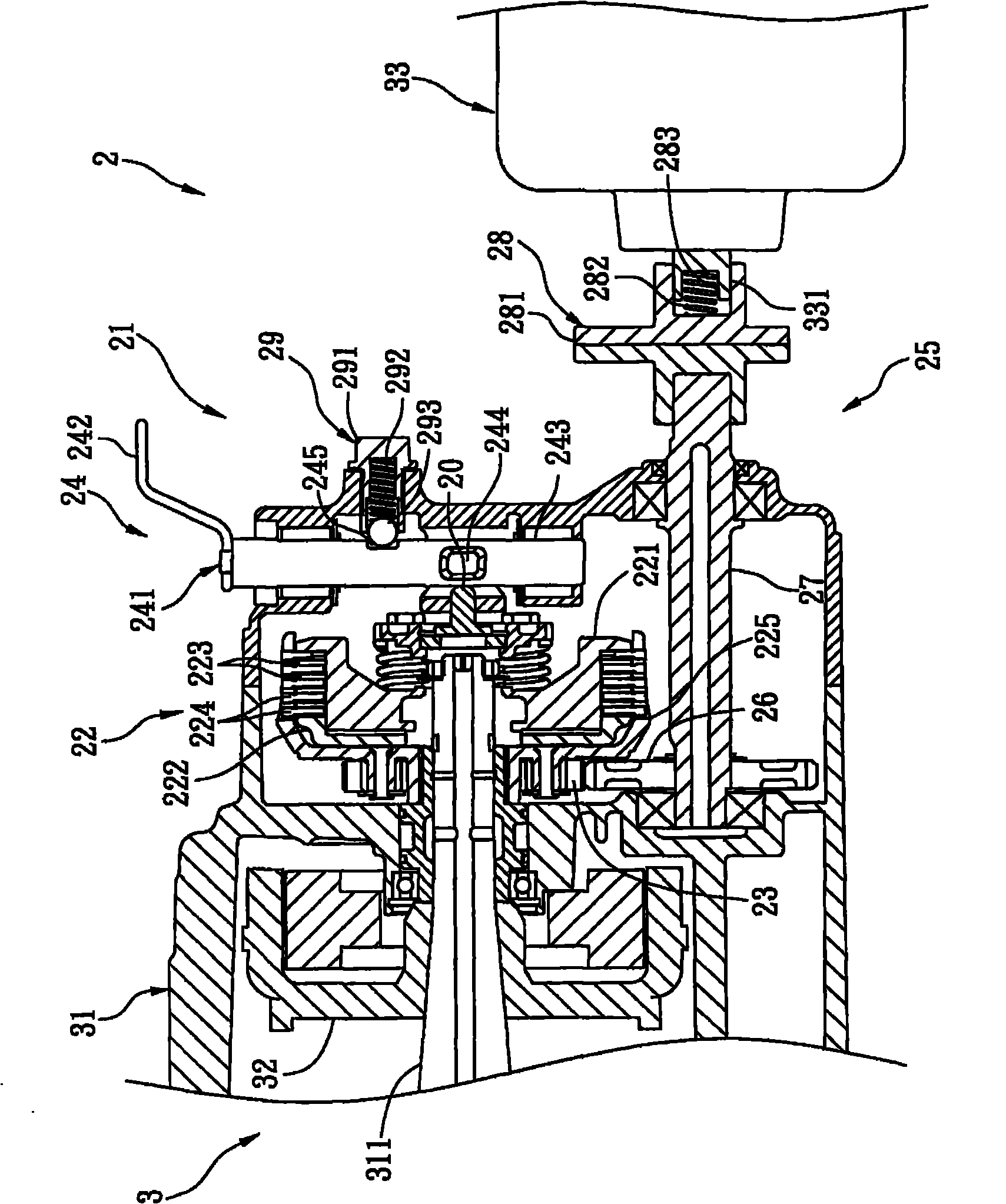
[0015] refer to figure 1 , a preferred embodiment of the power generating device 2 of the vehicle of the present invention, the vehicle 3 includes an engine 31 with a crankshaft 311, a charging generator 32 arranged on the crankshaft 311, and a motor driven by the engine 31 Power generator 33. Wherein, the electric power generated by the charging generator 32 is used to charge the battery (not shown) of the vehicle 3 . The rotating shaft 331 of the power generator 33 is not coaxial with the crankshaft 311 .

[0016] The generating device 2 includes a clutch unit 21 disposed outside the crankshaft 311 and a transmission unit 25 .

[0017] The clutch unit 21 includes a switching clutch 22 arranged on the crankshaft 311, a driving gear 23 arr...


PUM


Abstract

A power generation device of a vehicle is disclosed. The vehicle comprises: an engine possessing a crankshaft, a generator which is used for charging and one generator used for providing power. The power generation device comprises: a clutch unit and a transmission unit. The clutch unit comprises: a switching clutch, a driving gear which is arranged on the switching clutch and a switching mechanism which can actuate the switching clutch. The transmission unit comprises: a driven gear which is engaged with the driving gear and an input shaft which is moved under the influence of the driven gear. Because a rotating shaft of the generator used for providing power is different with the crankshaft, conditions of insufficient intensity and breakage caused by the overlength crankshaft can be avoided and a problem of large-scale configuration of the engine and the generator used for providing power can be avoided too. The clutch unit can be used to manually control generating so as to avoid oil consumption.

Description

technical field [0001] The present invention relates to a power generating device, in particular to a vehicle power generating device. Background technique [0002] The US Publication No. US6820576 "Vehicle Driven by Internal Combustion Engine with Generator" discloses a technology for driving a non-vehicle generator by the internal combustion engine of the vehicle. [0003] A vehicle driven by an internal combustion engine comprising a power conversion element interposed between a crankshaft of the internal combustion engine and drive wheels and having a centrifugal clutch connecting the crankshaft and the drive wheels, a generator driven by the internal combustion engine, and A control element capable of controlling the internal combustion engine. The control element utilizes the speed of the internal combustion engine to control the internal combustion engine to switch between a vehicle driving mode and a generator driving mode. [0004] Although it can achieve the effe...

Claims


Application Information

Patent Timeline
Patent Type & Authority Applications(China)
IPC IPC(8): H02K7/18
Inventor 张记函何昭昌赖建宏
Owner KYMCO
Why Eureka
Eureka Blog
Learn More