Method for monitoring wind turbines

A technology of wind turbines and control units, applied in the direction of wind engines, wind motor combinations, wind turbine components, etc., which can solve problems such as expensive, vulnerable to failures, computers, etc.

Inactive Publication Date: 2012-02-01
SUZLON ENERGY LTD
View PDF9 Cites 15 Cited by
  • Summary
  • Abstract
  • Description
  • Claims
  • Application Information

AI Technical Summary

Problems solved by technology

[0009] Because the methods known in the prior art involve expensive computing operations, expensive, fault-prone computers are often required in order to perform them

Method used


Image

  • Method for monitoring wind turbines
  • Method for monitoring wind turbines
  • Method for monitoring wind turbines

Examples


Embodiment Construction

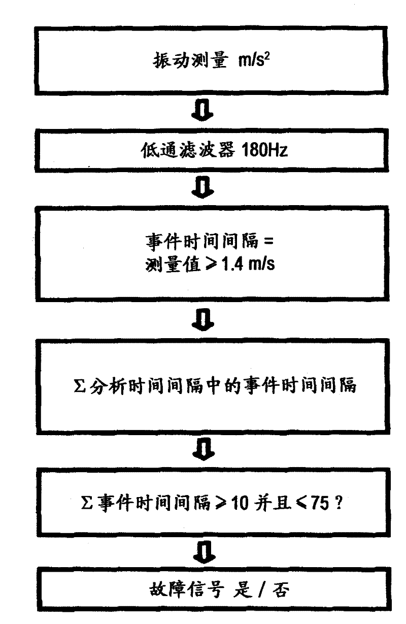
[0058] exist figure 1 In , the necessary steps of the method according to the invention for monitoring a wind turbine 3 are described. In order to be able to check each individual rotor blade of the wind turbine 3 for possible rotor blade damage, the wind turbine 3 is equipped with at least one acceleration sensor 10 which measures the vibrations of the individual rotor blades with a sampling frequency of at least 10 kHz. Next, the measurement results are introduced through a 180Hz low-pass filter.

[0059] Acquisition in which the measured value is always over 1.4m / s 2 The time interval of is used as the event time interval. During the 5 min analysis time interval, count event time intervals. If the number of event time intervals in the evaluation time interval corresponds to a value between 10 and 75, a fault signal is output.

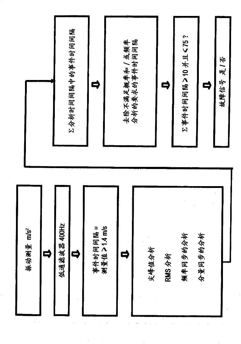
[0060] figure 2 An expanded embodiment of the method according to the invention is shown which, in addition to the analysis step in the time d...


PUM


Abstract

The invention relates to a method for monitoring at least one wind turbine and to a device and a system for monitoring at least one wind turbine. The aim of the invention is to provide a method for detecting damage to rotor blades which can be realized in a hardware device which is simple, cost-effective and less susceptible to faults. A further objective is to provide another method for detecting damage to rotor blades. Said objective is achieved by a method comprising the method steps according to claim 1 of the patent application and by a device and a system for monitoring wind turbines according to the claims 12 and 14. According to the present invention, the method for detecting damage to rotor blades comprises analysis steps performed exclusively in the time range.

Description

technical field [0001] The invention relates to a method for monitoring at least one wind turbine, a device and a system for monitoring at least one wind turbine. Background technique [0002] For the economical operation of wind turbines such as wind farms, it is important to be able to determine damage and breakage of the rotor blades of the wind turbine at the earliest possible point in time. Only through timely detection of damage can maintenance costs be kept low and consequential losses avoided. [0003] One possibility of detecting damages and cracks in the rotor blades consists in monitoring the condition of the rotor blades by means of frequent visual inspections on site. [0004] However, these visual inspections are expensive and for this reason are not desirable. Since a damaged or cracked rotor blade causes vibrations in the rotor blade during operation, it is known from the prior art to use this vibration to automatically check the condition of the rotor blad...

Claims


Application Information

Patent Timeline
Patent Type & Authority Applications(China)
IPC IPC(8): F03D9/00G01H1/08
CPCF05B2260/83F03D11/00G01H1/003F05B2260/80Y02E10/722F05B2260/96F03D17/00
Inventor J·温克尔曼M·胡恩
Owner SUZLON ENERGY LTD
Why Eureka
Try Eureka