
Hydrodynamic foil bearing assembly

A technology for foil bearings, bearing assemblies, applied in the direction of bearing elements, bearings, shafts and bearings, etc.

Inactive Publication Date: 2012-02-01
SIEMENS AG
View PDF7 Cites 1 Cited by
  • Summary
  • Abstract
  • Description
  • Claims
  • Application Information

AI Technical Summary

Problems solved by technology

This leads to dry friction during the start and stop cycles, which inevitably leads to intense surface wear of the foil bearings

Method used


Image

  • Hydrodynamic foil bearing assembly
  • Hydrodynamic foil bearing assembly
  • Hydrodynamic foil bearing assembly

Examples


Embodiment Construction

[0042] Various embodiments are described with reference to the drawings, wherein like reference numerals are used to refer to like elements throughout. In the following description, for purposes of explanation, numerous specific details are set forth in order to provide a thorough understanding of one or more embodiments. It is apparent that the embodiments may be practiced without these specific details.

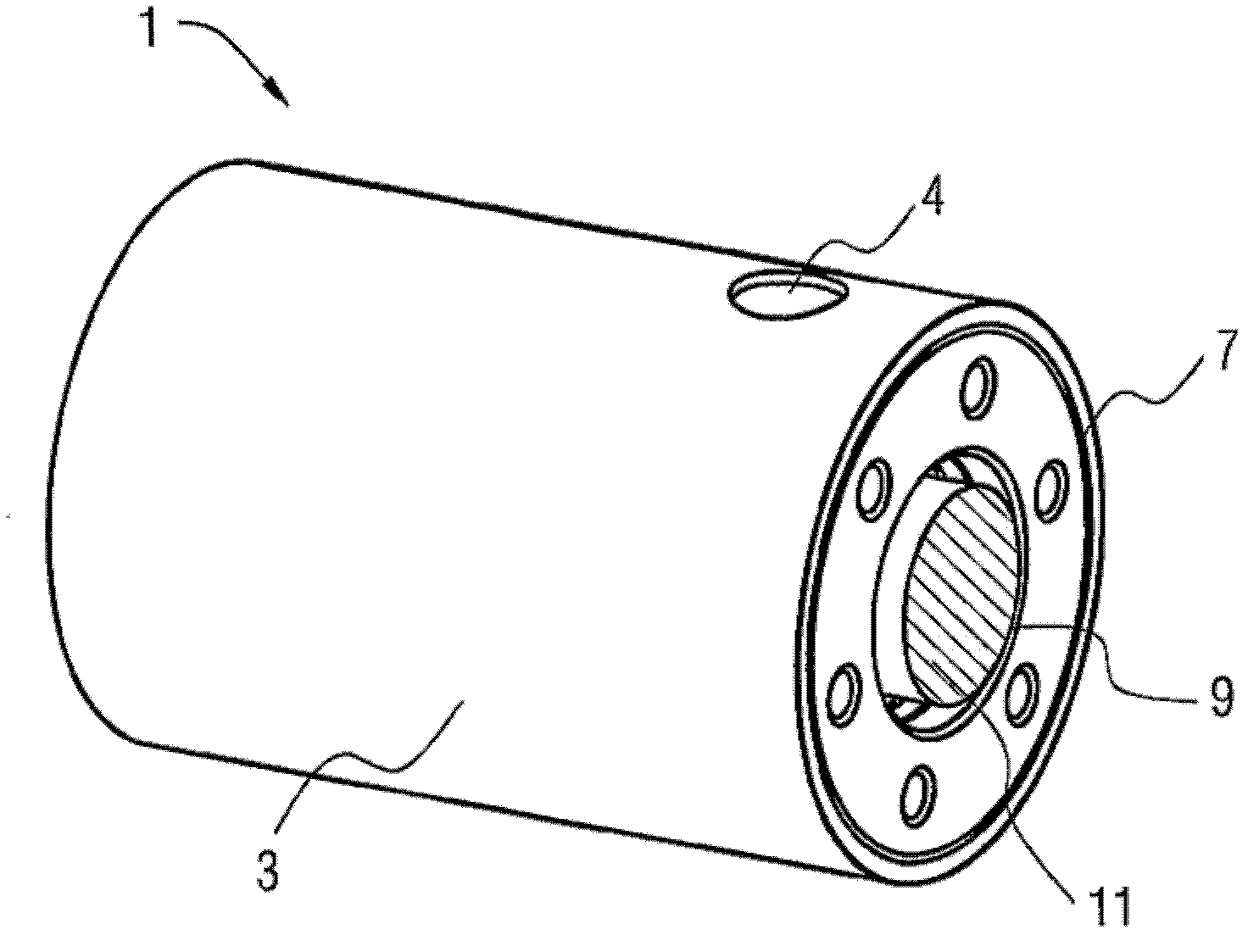
[0043] figure 1 A perspective view of a hydrodynamic foil bearing assembly according to embodiments herein is shown. The hydrodynamic foil bearing assembly 1 comprises a bearing housing 3 and an opening 4 . The bearing housing 3 typically comprises a cylindrical hollow section and at least one foil (not shown) delimiting the cylindrical hollow space for receiving the rotating shaft 11 arranged inside the bearing housing 1 . A gap is defined between the inner wall surface of at least one foil and the outer circumference of the rotating shaft 11 .

[0044] In one embodime...


PUM


Abstract

A bearing housing of a hydrodynamic foil bearing assembly has an opening for allowing flow of a fluid into the bearing housing. Also included in the a hydrodynamic foil bearing assembly is at least one foil having at least one opening and defining a cylindrical hollow space for receiving a rotating shaft therein. Fluid is supplied from the opening of the bearing housing to a gap between the at least one foil and the rotating shaft through the at least one opening of the at least one foil to form a pressurized fluid film therein.

Description

technical field [0001] The present invention relates to hydrodynamic foil bearing assemblies for rotating machinery. Background technique [0002] Hydrodynamic foil bearings have been proposed to improve conventional hydrodynamic bearings for high speed rotating systems. The working principle of foil bearings is based on the formation of a thin film of pressurized fluid in the annular gap between the outer circumference of the rotating shaft and the bearing surface formed by a plurality of foils or a single bump foil. This film of pressurized fluid works as a lubricating layer, reducing friction between the outer circumference of the rotating shaft and the inner wall surface of the foil during operation, and allowing the bearing to efficiently support high loads. Due to this pressurized fluid film, the turning shaft turns while being suspended in the air and maintaining a predetermined distance from the foil. As the shaft rotates at a certain speed, a film of pressurized f...

Claims


Application Information

Patent Timeline
IPC IPC(8): F16C17/12
CPCF16C17/024F16C2300/02F16C32/0614F16C33/1005F16C39/04
Inventor V.V.马里宁
Owner SIEMENS AG
Learn More