Method for separating signal paths and use for improving speech using electric larynx

A technology of electronic larynx and voice signal, which is applied in the direction of voice analysis, larynx, and human body tubular structure devices, and can solve problems such as voice signal quality damage

Inactive Publication Date: 2012-02-01
FORSCHUNGSHLDG TU GRAZ
View PDF7 Cites 2 Cited by
  • Summary
  • Abstract
  • Description
  • Claims
  • Application Information

AI Technical Summary

Problems solved by technology

However, the quality of the speech s

Method used


Image

  • Method for separating signal paths and use for improving speech using electric larynx
  • Method for separating signal paths and use for improving speech using electric larynx
  • Method for separating signal paths and use for improving speech using electric larynx

Examples


Embodiment Construction

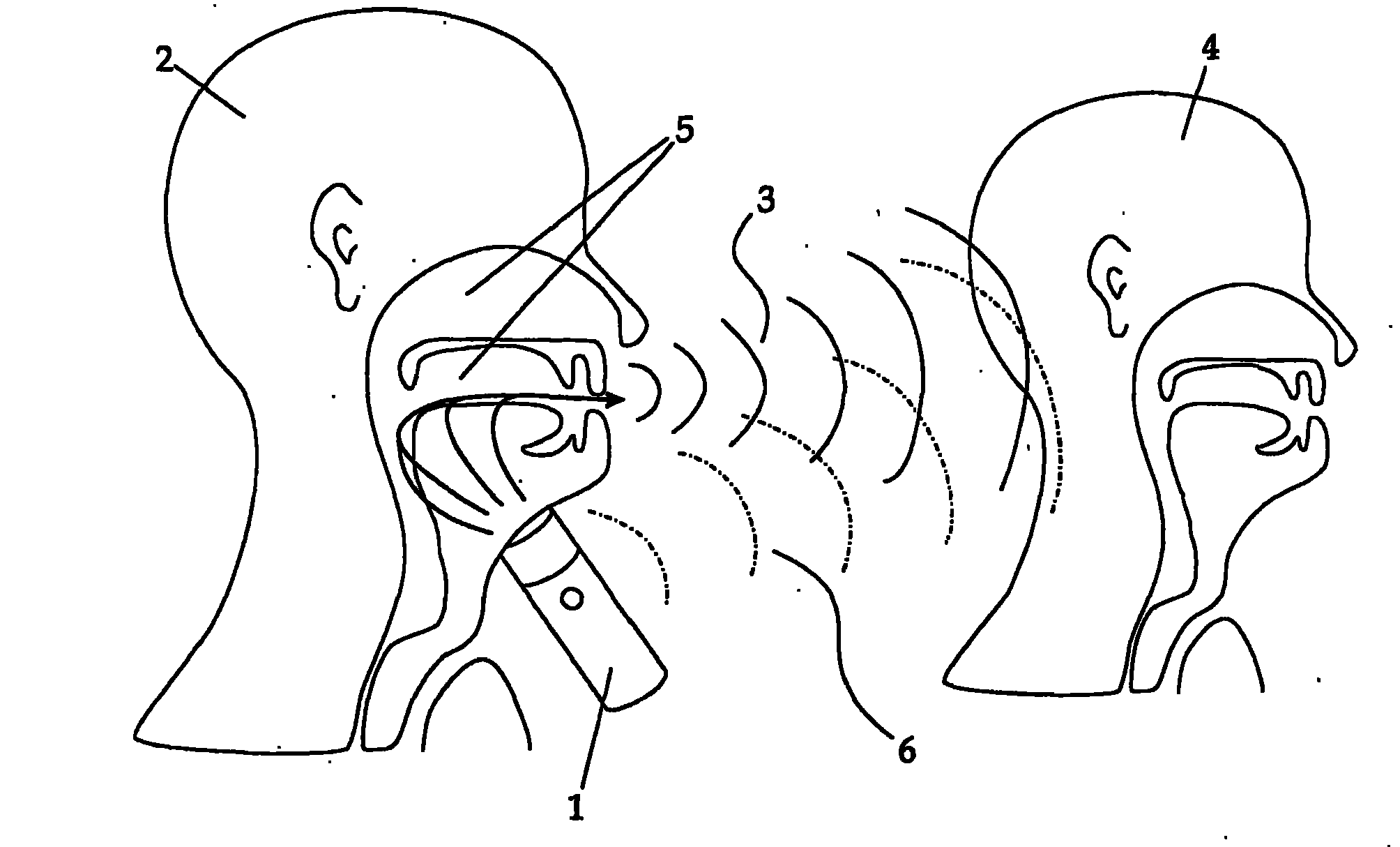
[0032] exist figure 1 The different transmission paths of the signal of EL 1 are shown in . Among them, EL 1 is set on the throat of speaker 2 . The sound waves generated by the EL 1 propagate on the one hand through the normal speech channels (mouth and nose) of the first speaker 2 and are pronounced there as speech; this first signal 3 is significantly or time-varying. At the ear of the listener 4, in addition to this time-varying signal 3 there is a second signal 6 of the direct sound wave of the EL 1 (at figure 1 ), this signal 4 is largely invariant and is therefore considered time-invariant. The second part 6 of the total signal (ie the basic noise of EL 1 ) is perceived by the listener 4 as an interfering signal and reduces the intelligibility of the speaker 2's speech. Thus, the original excitation by means of EL 1 is transmitted via two different paths.

[0033] The invention is of course concerned with improving the speech quality of an EL speaker in the context ...


PUM


Abstract

In order to improve the speech quality of an electric larynx (EL) speaker, the speech signal of which is digitized by suitable means, the following steps are carried out: a) dividing a single-channel speech signal into a series of frequency channels by transferring it from a time domain into a discrete frequency domain; b) filtering out the modulation frequency of the EL by way of a high-pass or notch filter, in each frequency channel; and c) back-transforming the filtered speech signal from the frequency domain into the time domain and combining it into a single-channel output signal.

Description

technical field [0001] The present invention relates to a method for improving the speech quality of an electronic larynx (EL) speaker, wherein the speaker's speech signal is digitized by suitable means. Suitable means here are, for example, a microphone with a corresponding analog-to-digital converter, a telephone or other methods using electronic equipment. Background technique [0002] An EL is a device used to create artificial surrogate sounds, eg for patients who have had their larynx surgically removed. Where the EL is placed on the underside of the jaw; a sound generator with a specific frequency causes the air in the oral cavity to vibrate on the underside of the jaw through the soft tissues. Then, this vibration is modulated by the speaking organ, and speech becomes possible. Because sound generators mostly operate at one frequency, the sound sounds flat and unnatural or "mechanical". [0003] A further disadvantage is that the vibrations of the EL interfere wit...

Claims


Application Information

Patent Timeline
IPC IPC(8): G10L21/02A61F2/20G10L25/03G10L25/18G10L25/93
CPCG10L25/18G10L25/03G10L21/0205G10L21/0364
Inventor M·哈格姆勒G·库宾
Owner FORSCHUNGSHLDG TU GRAZ
Why Eureka
Try Eureka