Wireless communication system, transmission device, and receiving device
A technology of a wireless communication system and a receiving device, which is applied in the direction of wireless communication, radio transmission system, diversity/multi-antenna system, etc., and can solve problems such as inability to use multiple antennas
- Summary
- Abstract
- Description
- Claims
- Application Information
AI Technical Summary
Problems solved by technology
Method used
Image
Examples
Embodiment approach 1
[0035] In this embodiment, a wireless communication system is described in which the number of transmitting antennas of the transmitting device is M and the number of spatial multiplexing is 1, and the number of receiving antennas of the receiving device is N and the number of spatial multiplexing is 1. When the number is 1, a multipath transmission countermeasure is implemented in the modulation unit and the demodulation unit.
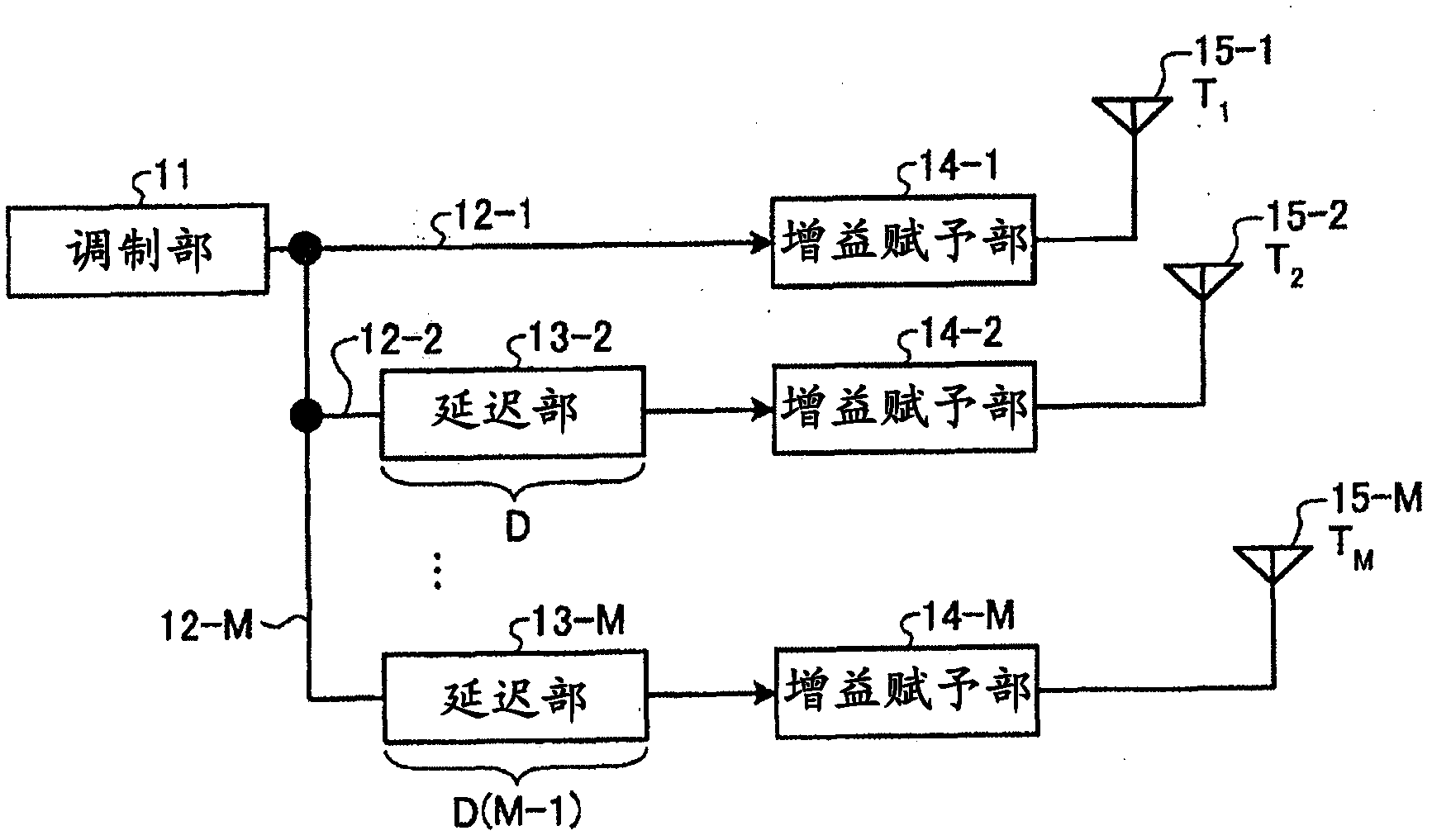
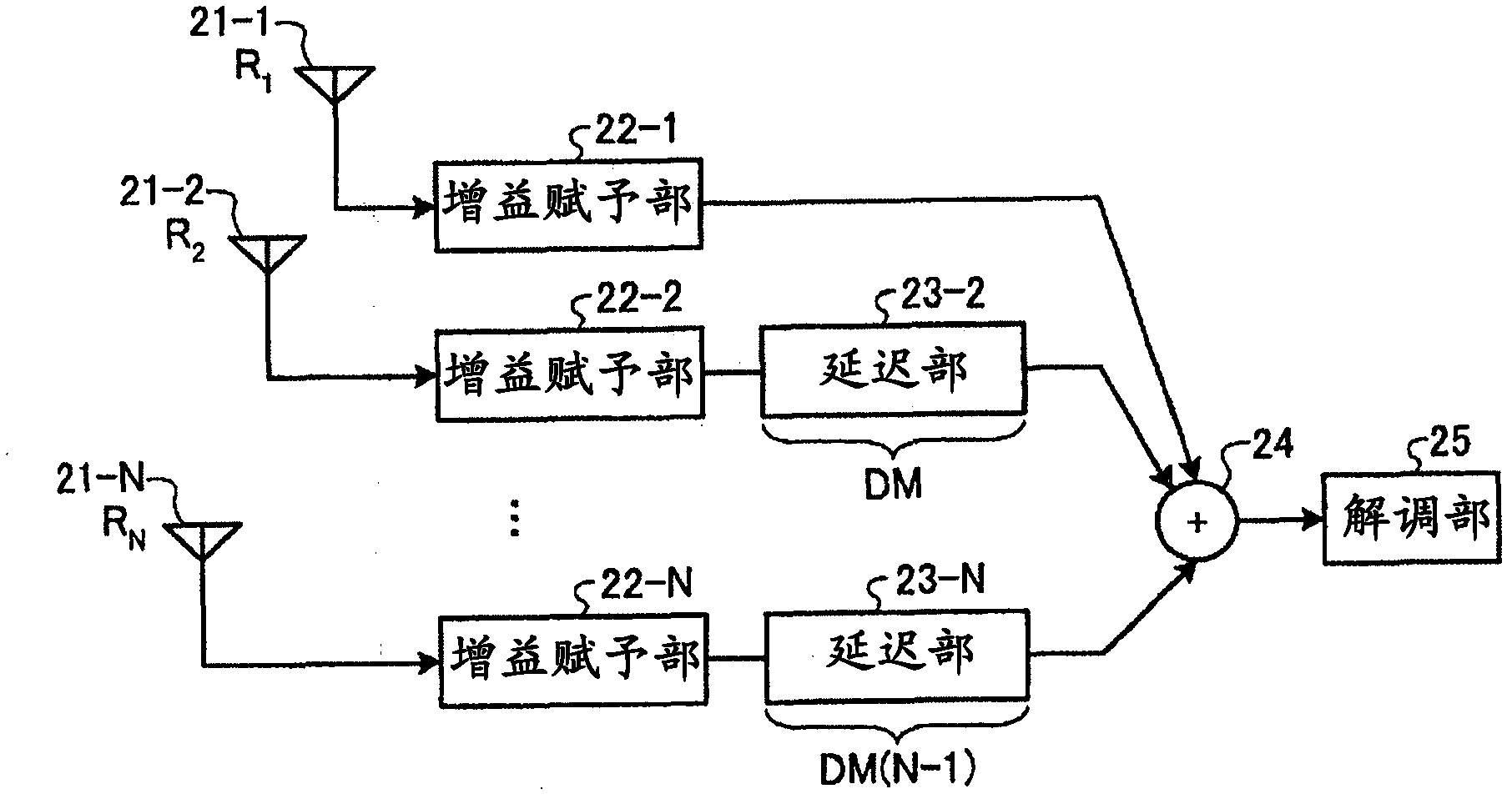
[0036] figure 1 It is a diagram showing a configuration example of a radio communication system according to the present embodiment. It includes: a transmitting device equipped with M transmitting antennas, and a receiving device equipped with N receiving antennas. Next, each device will be specifically described.
[0037] figure 2 It is a figure which shows the structural example of a transmission apparatus. The transmission device includes a modulation unit 11, signal lines 12-1 to 12-M, delay units 13-2 to 13-M, gain imparting units 14-1 to 14...
Embodiment approach 2
[0054] In the present embodiment, different delay amounts from those in the first embodiment are given to the transmitting device and the receiving device. Portions different from Embodiment 1 will be described.
[0055] Figure 6 It is a figure which shows the structural example of a transmission apparatus. The transmission device includes a modulation unit 11, signal lines 12-1 to 12-M, delay units 41-2 to 41-M, gain imparting units 14-1 to 14-M, and transmission antennas 15-1 to 15-M. Delay units 41-2 to 41-M perform delay processing on transmission signals.
[0056] Figure 7 It is a figure which shows the structural example of a receiving apparatus. The receiving device includes receiving antennas 21 - 1 to 21 -N, gain imparting units 22 - 1 to 22 -N, delaying units 51 - 2 to 51 -N, adding unit 24 , and demodulating unit 25 . Delay sections 51-2 to 51-N perform delay processing on received signals.
[0057] In the transmission device, the signal lines 12-2 to 12-M i...
Embodiment approach 3
[0064] In this embodiment, a wireless communication system will be described in which the number of transmitting antennas of the transmitting device is LK, the number of outputs of the modulator is L, and the number of receiving antennas of the receiving device is PQ. , assuming that the number of inputs of the demodulation unit is P, MIMO (Multiple Input Multiple Output) spatial multiplexing transmission is performed in the modulation unit and the demodulation unit, and demodulation processing in the frequency domain is performed in the receiving device . Portions different from Embodiment 1 will be described.
[0065] Figure 9 It is a figure which shows the structural example of a transmission apparatus. The transmission device includes a modulation unit 61, signal lines 62-1 to 62-LK, delay units 63-2 to 63-K, 63-K+2 to 63-K+K, . . . , 63-(L-1) K+2 to 63-LK, gain imparting units 64-1 to 64-LK, and transmission antennas 65-1 to 65-LK. The modulation unit 61 generates a ...
PUM
 Abstract
Description
Claims
Application Information
 - R&D
- Intellectual Property
- Life Sciences
- Materials
- Tech Scout
- Unparalleled Data Quality
- Higher Quality Content
- 60% Fewer Hallucinations
Browse by: Latest US Patents, China's latest patents, Technical Efficacy Thesaurus, Application Domain, Technology Topic, Popular Technical Reports.
© 2025 PatSnap. All rights reserved.Legal|Privacy policy|Modern Slavery Act Transparency Statement|Sitemap|About US| Contact US: help@patsnap.com


