Inner cavity cleaning clamp for high-pressure oil pipe

A technology for high-pressure oil pipes and cleaning fixtures, used in cleaning methods and utensils, cleaning hollow objects, chemical instruments and methods, etc., can solve the problems of high pressure, high sealing requirements between cleaning equipment and oil pipes, etc., to achieve convenient use and ensure cleanliness High degree of requirements, simple and convenient loading and unloading effect

Inactive Publication Date: 2012-02-08
JIANGSU HONGFENG AOKAI ELECTROMECHANICAL
View PDF4 Cites 2 Cited by
  • Summary
  • Abstract
  • Description
  • Claims
  • Application Information

AI Technical Summary

Problems solved by technology

However, due to the high pressure of the cleaning fluid during cleaning, the sealing between the cleaning equipment and the oil pipe is very high.

Method used


Image

  • Inner cavity cleaning clamp for high-pressure oil pipe
  • Inner cavity cleaning clamp for high-pressure oil pipe
  • Inner cavity cleaning clamp for high-pressure oil pipe

Examples


Embodiment Construction

[0013] The present invention will be further described below in conjunction with specific drawings and embodiments.

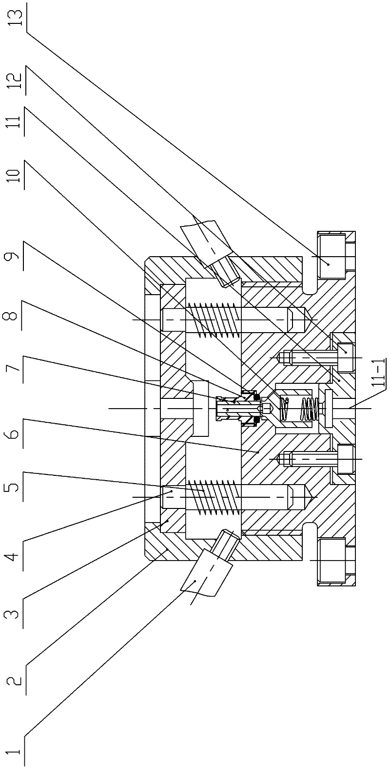
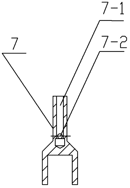
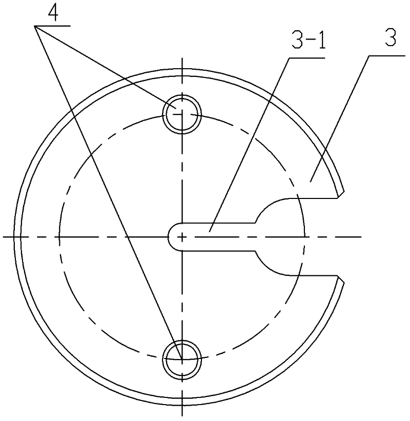
[0014] Such as figure 1 , as shown in 2, the high-pressure oil pipe inner cavity cleaning fixture includes a fixture body 6, a spool 7 is located at the center of the fixture body 6, the upper end of the spool 7 is covered with a joint 8, and the lower part of the joint 8 is threaded with the fixture body 6. A sealing ring 9 is sheathed around the waist of the valve core 7, and the sealing ring 9 is located in the gap between the lower part of the joint 8 and the fixture body. There is a gap between the lower part of the valve core 7 and the fixture body 6, and a bottom plate 11 is provided under the valve core 7, on which one end of the first compression spring 10 (1.5*8*15GB2089) is fixed, and the other end of the first compression spring 10 is Support the lower end of the spool 7. The bottom plate 11 is fixed to the main body 6 by M6 socket head cap screws...


PUM


Abstract

The invention relates to an inner cavity cleaning clamp for a high-pressure oil pipe. A valve core is positioned in the center of a clamp body; a joint is sleeved at the upper end of the valve core; the lower part of the joint is in threaded connection with the clamp body; a sealing ring is sleeved on the waist part of valve core, and is positioned in a crack between the lower part of the joint and clamp body; a gap is formed between the lower part of the valve core and the clamp body; a bottom plate is arranged below the valve core, and is fixed with the clamp body; one end of a first compression spring is fixed on the bottom plate; the other end of the spring is pressed against the lower end of the valve core; a cavity is formed in the upper part of the valve core; the side wall of the valve core is provided with a valve core through hole for communicating cavities outside and inside the valve core; the valve core through hole is sealed with the sealing ring when valve core is jacked up by the first compression spring; the clamp body is provided with a pressure plate; two guide posts are arranged below the pressure plate; the lower ends of the guide posts are inserted into the clamp body; second compression springs are sleeved on the guide posts; and the upper end of the pressure plate is pressed by a compression cap. The inner cavity cleaning clamp has the advantages of capability of meeting the requirement of inner cavity cleaning of the high-pressure oil pipe, simple structure, easiness and convenience for assembling and disassembling a mold, safety and reliability.

Description

technical field [0001] The invention relates to a fixture, in particular to a fixture for cleaning the inner cavity of a high-pressure oil pipe. Background technique [0002] At present, the cleaning of the inner cavity of the steel pipe is mainly carried out by sand blasting and chip blowing, which increases the use of labor force, low efficiency and high cost. The use of grease cleaning fluid for cleaning is relatively easy to operate, low in cost and good in effect. However, since the cleaning liquid requires a high pressure during cleaning, the sealing between the cleaning equipment and the oil pipe is highly required. Contents of the invention [0003] The purpose of the present invention is to overcome the deficiencies in the prior art, and provide a high-pressure oil pipe inner cavity cleaning fixture, which uses a special cleaning liquid for the inner cavity of the oil pipe to clean the inner cavity of the oil pipe to prevent rust and remove impurities. [0004] ...

Claims


Application Information

Patent Timeline
Patent Type & Authority Applications(China)
IPC IPC(8): B08B9/032
Inventor 赵新权
Owner JIANGSU HONGFENG AOKAI ELECTROMECHANICAL
Why Eureka
Try Eureka