Method for monitoring oil-gas pipeline in mining subsidence area
A technology for oil and gas pipelines and subsidence areas, which can be used in pipeline systems, measuring devices, optical devices, etc., and can solve problems such as optical fiber grating sensing not seen
- Summary
- Abstract
- Description
- Claims
- Application Information
AI Technical Summary
Problems solved by technology
Method used
Image
Examples
Embodiment
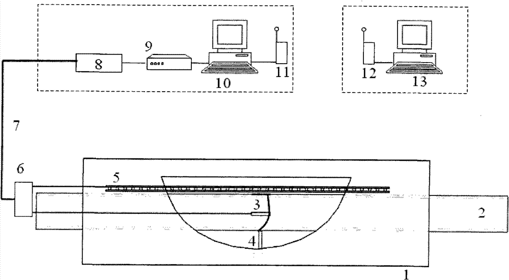
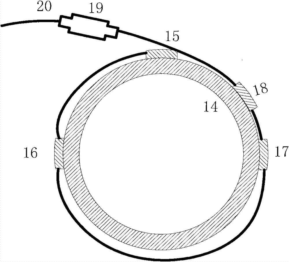
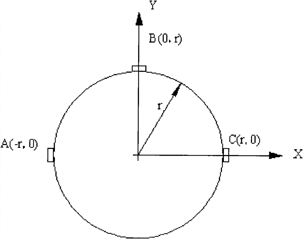
[0112] Embodiment. This example is an experimental method, as Figure 1-Figure 3 shown. The test was carried out in a goaf subsidence area with mining depth ratio of 10, mining length of 15m, pipeline buried depth of 3m and pipeline length of 130m. The diameter of the pipeline is 168mm, the wall thickness is 6mm, and the steel grade is L245.
[0113]The oil and gas pipeline monitoring system in the goaf subsidence area is divided into an on-site collection and transmission system and a remote receiving and analysis system, including pipe strain monitoring devices, pipe-soil relative displacement monitoring devices, horizontal deformation monitoring devices in goaf subsidence areas, on-site monitoring stations, and office facilities. Receiving terminal (host computer).
[0114] The overall composition of the oil and gas pipeline monitoring system in the goaf subsidence area is as follows: figure 2 shown. Install the fiber grating strain sensor a3 and the pipe-soil relative ...
PUM
 Abstract
Description
Claims
Application Information
 - R&D
- Intellectual Property
- Life Sciences
- Materials
- Tech Scout
- Unparalleled Data Quality
- Higher Quality Content
- 60% Fewer Hallucinations
Browse by: Latest US Patents, China's latest patents, Technical Efficacy Thesaurus, Application Domain, Technology Topic, Popular Technical Reports.
© 2025 PatSnap. All rights reserved.Legal|Privacy policy|Modern Slavery Act Transparency Statement|Sitemap|About US| Contact US: help@patsnap.com


