Zooming lens, optical apparatus and method of manufacturing zooming lens

A zoom lens and focal length technology, applied in optics, optical components, instruments, etc., can solve the problems of increased variation and inability to obtain optical performance, and achieve good optical performance, suppress variation, phantom and stray light

Active Publication Date: 2012-02-08
NIKON CORP
View PDF17 Cites 13 Cited by
  • Summary
  • Abstract
  • Description
  • Claims
  • Application Information

AI Technical Summary

Problems solved by technology

[0011] When a conventional zoom lens is forcibly made to have a high zoom ratio, variation in aberration increases, and thus sufficiently high optical performance cannot be obtained
In addition, there is a problem that reflected light that produces ghosts and stray light is easily generated from the optical surface in such a zoom lens

Method used


Image

  • Zooming lens, optical apparatus and method of manufacturing zooming lens
  • Zooming lens, optical apparatus and method of manufacturing zooming lens
  • Zooming lens, optical apparatus and method of manufacturing zooming lens

Examples


no. 1 example

[0084] A zoom lens according to a first embodiment of the present application is described below.

[0085] The zoom lens according to the first embodiment of the present application includes, in order from the object side along the optical axis, a first lens group having positive refractive power, a second lens group having negative refractive power, and a lens group having positive refractive power. Power of the third lens group. When zooming from the wide-angle end state to the telephoto end state, the distance between the first lens group and the second lens group increases, and the distance between the second lens group and the third lens group decreases. With this configuration, it becomes possible to realize an optical system capable of zooming, and at the same time suppress a change in distortion generated upon zooming.

[0086] In the zoom lens according to the first embodiment, the first lens group includes the positive lens A satisfying the following conditional exp...

example 1

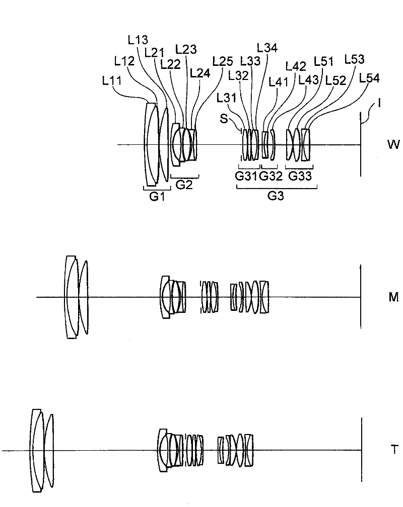
[0255] figure 1 is a sectional view showing the lens configuration of the zoom lens according to Example 1 of the first embodiment of the present application.

[0256] like figure 1 As shown in , the zoom lens according to Example 1 of the first embodiment is composed of, in order from the object side along the optical axis: a first lens group G1 having positive refractive power, a first lens group G1 having negative refractive power, The second lens group G2 with positive refractive power and the third lens group G3 with positive refractive power. The third lens group G3 is composed of, in order from the object side along the optical axis: a front lens group G31 having positive refractive power, an intermediate lens group G32 having negative refractive power, and a front lens group G32 having positive refractive power. Power of the rear lens group G33.

[0257] When zooming from the wide-angle end state to the telephoto end state, with respect to the image plane I, the fir...

example 2

[0287] Figure 4 is a sectional view showing the lens configuration of the zoom lens according to Example 2 of the first embodiment of the present application.

[0288] like Figure 4 As shown in , the zoom lens according to Example 2 of the first embodiment is composed of, in order from the object side along the optical axis: a first lens group G1 having positive refractive power, a first lens group G1 having negative refractive power, The second lens group G2 with positive refractive power and the third lens group G3 with positive refractive power. The third lens group G3 is composed of, in order from the object side along the optical axis, a front lens group G31 having positive refractive power and a rear lens group G32 having positive refractive power.

[0289] When zooming from the wide-angle end state to the telephoto end state, with respect to the image plane I, the first lens group G1 moves monotonously toward the object side, the second lens group G2 moves monotonic...


PUM


Abstract

The invention provides a zooming lens, which comprises a first lens group G1 having positive refractive power, a second lens group G2 having negative refractive power and a third lens group G3 having positive refractive power successively arranged along an optical axis. When zooming from a wide-angle end state W to a telephoto end state T, the distance between the first lens group G1 and the second lens group G2 is increased and the distance between the second lens group G2 and the third lens group G3 is reduced. Given conditions are satisfied. Therefore, the zooming lens is high in optical performance and can inhibit the aberration variation. The invention also provides an optical apparatus equipped with the zooming lens and a method for manufacturing the zooming lens.

Description

[0001] The disclosures of the following priority applications are hereby incorporated by reference: [0002] Japanese Laid-Open Patent Application No. 2010-171323 filed on July 30, 2010; [0003] Japanese Laid-Open Patent Application No. 2010-171324 filed on July 30, 2010; [0004] Japanese Laid-Open Patent Application No. 2010-171336 filed on July 30, 2010; [0005] Japanese Laid-Open Patent Application No. 2010-097333 filed on April 25, 2011; [0006] Japanese Laid-Open Patent Application No. 2011-151892 filed on July 8, 2011; [0007] Japanese Laid-Open Patent Application No. 2011-151899 filed on July 8, 2011; and [0008] Japanese Laid-Open Patent Application No. 2011-151906 filed on July 8, 2011. technical field [0009] The present invention relates to a zoom lens, an optical device equipped with a zoom lens and a method for manufacturing the zoom lens. Background technique [0010] Various zoom lenses having a lens group having positive refractive power arranged ...

Claims


Application Information

Patent Timeline
Patent Type & Authority Applications(China)
IPC IPC(8): G02B15/173G02B15/04
Inventor 小滨昭彦横井规和田中一政
Owner NIKON CORP
Why Eureka
Try Eureka