Microswitch trigger device

A technology of triggering device and micro switch, applied in electronic switches, electrical components, pulse technology, etc., can solve problems such as contact aging, metal shrapnel loss of elasticity, and trigger switch failure.

Inactive Publication Date: 2013-12-25
GUANGDONG VTRON TECH CO LTD
View PDF4 Cites 0 Cited by
  • Summary
  • Abstract
  • Description
  • Claims
  • Application Information

AI Technical Summary

Problems solved by technology

[0003] Applying this micro switch trigger method requires an external force greater than a specific threshold to trigger the switch, and the trigger force is related to the elastic coefficient design of the shrapnel, and it needs to be greater than a specific stroke to make the shrapnel contact with the contact to trigger the switch. The triggering principle of the switch is realized by the mechanical contact between the shrapnel and the contact, and the stroke is generally not less than 0.5mm. Frequent pressing will also cause the metal shrapnel to fatigue and lose elasticity and the contact to age, resulting in the failure of the trigger switch.

Method used


Image

  • Microswitch trigger device
  • Microswitch trigger device
  • Microswitch trigger device

Examples


Embodiment Construction

[0011] The solution of the present invention will be described in detail below with one of the preferred embodiments.

[0012] The basic idea of ​​the solution of the present invention is to adopt a capacitor structure, and realize the triggering of the micro switch through the change of the capacitance of the capacitor.

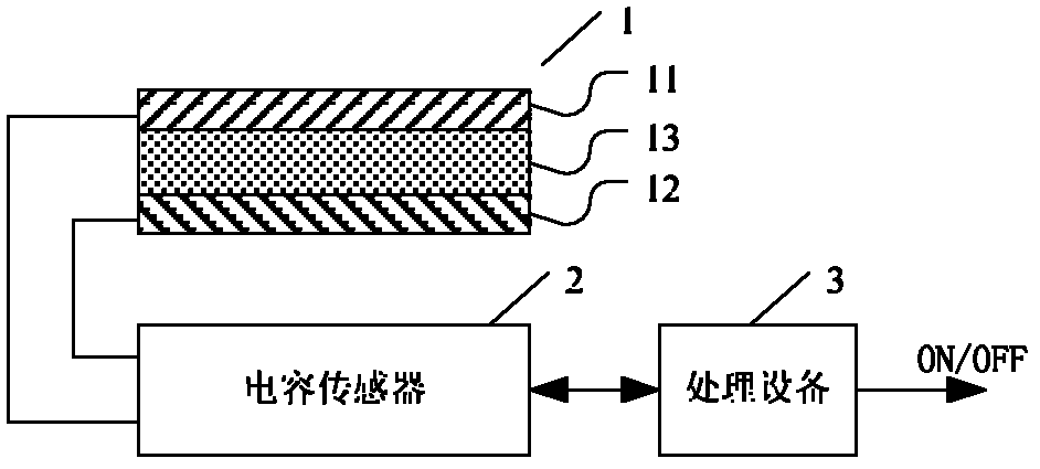
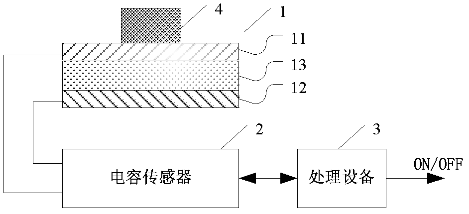
[0013] see figure 2 As shown, it is a structural schematic diagram of the first embodiment of the microswitch trigger device of the present invention, which includes: a capacitor 1, a capacitive sensor 2 connected to the capacitor 1 to detect the capacitance of the capacitor 1, and a capacitive sensor 2 The connected processing device 3, the processing device 3 generates a switch trigger signal according to the variation of the capacitance of the capacitor body 1, figure 2 As shown, the capacitor 1 includes a movable electrode 11 , a fixed electrode 12 and an elastic medium 13 sandwiched between the movable electrode 11 and the fixed electrode 12 .

[00...


PUM


Abstract

The invention discloses a microswitch trigger device, comprising a capacitor body, a capacitor sensor connected with the capacitor body and used for detecting the capacitance of the capacitor body, and processing equipment connected with the capacitor sensor, wherein the processing equipment is used for generating a switch triggering signal according to the variation of the capacitance of the capacitor body; and the capacitor body comprises a movable electrode, a fixed electrode and an elastic medium clamped between the movable electrode and the fixed electrode. According to the scheme provided by the invention, when a switch is triggered, the displacement between the movable electrode and the fixed electrode is subjected to tiny change by pressing the movable electrode or the fixed electrode of the capacitor body, so that the capacitance of the capacitor body changes, the capacitor sensor is used for detecting the changed capacitance, the processing equipment is used for generating the switch triggering signal according to the variation of the capacitance, and thus, a microswtich is triggered; and according to the realization manner in such a way, the switch is triggered according to the variation of the capacitance, so that the trigger is realized in a micro travel and micro external force manner.

Description

technical field [0001] The invention relates to a micro switch trigger device. Background technique [0002] Commonly used micro switches are triggered by light touch switches, such as mouse buttons, mobile phone buttons, etc. The light touch switch is an electronic switch, and the metal shrapnel in its internal structure bounces to achieve on-off figure 1 The schematic diagram of the light touch switch is shown in . In the illustration, when using it, press the switch button 2 lightly. After the switch button 2 moves, the internal shrapnel 3 moves, so that the shrapnel 3 contacts the metal contact 6 to realize the switch. When you let go of your hand and release the button 2, the elastic force of the shrapnel 3 recovers and leaves the contact 6, so that the switch is turned off. [0003] Applying this micro switch trigger method requires an external force greater than a specific threshold to trigger the switch, and the trigger force is related to the elastic coefficient de...

Claims


Application Information

Patent Timeline
Patent Type & Authority Patents(China)
IPC IPC(8): H03K17/965
Inventor 叶耀斌
Owner GUANGDONG VTRON TECH CO LTD
Why Eureka
Try Eureka