Vacuum heat insulating low-temperature pipe joint

A technology of vacuum heat insulation and cryogenic pipes, which is applied in the direction of pipes/pipe joints/fittings, non-detachable pipe connections, and pipes protected by heat insulation, etc. It can solve the problems of large heat leakage, high cost, and difficult operation at the joints. Achieve low heat leakage, easy installation, simple and beautiful appearance

Active Publication Date: 2012-02-15
杭州杭氧低温液化设备有限公司
View PDF6 Cites 17 Cited by
  • Summary
  • Abstract
  • Description
  • Claims
  • Application Information

AI Technical Summary

Problems solved by technology

The joints of the above structure have defects such as high cost, complex structure, high manufacturing precision, and large heat leakage at the joint, and a section of vacuum hose is required to complete the installation during pipeline installation.
[0006] In addition, if there is a large deviation in the size of the above two structures during production, it needs to be adjusted at the connection between the outlet end of the pipeline and the equipment, and the operation is relatively difficult.

Method used


Image

  • Vacuum heat insulating low-temperature pipe joint
  • Vacuum heat insulating low-temperature pipe joint
  • Vacuum heat insulating low-temperature pipe joint

Examples


Embodiment Construction

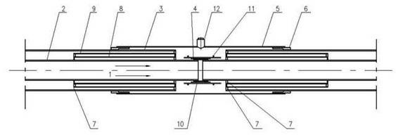
[0015] The present invention will be described in detail below in conjunction with accompanying drawing: image 3 As shown, the present invention includes an inner tube 2 for cryogenic liquid 1 to pass through, and two outer tubes 3 that are sleeved outside the inner tube 2 and connected together, and a vacuum space is formed between the inner and outer tubes; The joints of the two inner tubes 2 are welded together by a sleeve 4; the two outer tubes 3 are sleeved with a thermal insulation tube 5 at the joint, and two ends of the thermal insulation tube 5 are respectively provided with a 3 Welding ring 6 for outer wall welding.

[0016] image 3 Between the ends of the joints of the two outer pipes 3 shown and the walls of the inner pipe 2 are respectively provided with a section of inner heat-insulating pipe 8 and an outer heat-insulating pipe 9 that are nested with each other and extend to the two outer sides through the flange ring 7 to form the inner pipe 2 and the vacuum...


PUM


Abstract

The invention discloses a vacuum heat insulating low-temperature pipe joint, which comprises inner pipes for low-temperature liquid to flow through and outer pipes sleeved outside the inner pipes and connected with the inner pipes, wherein a vacuum space is formed between each inner pipe and each outer pipe; spliced positions of the two inner pipes are welded together through a bushing; heat preserving barrels are sleeved on the joints of the two outer pipes; the two end parts of each heat preserving barrel are provided with a welded loop which is welded with the outer walls of the outer pipes respectively; a section of internal heat isolating pipe and a section of external heat isolating pipe which are sleeved together and extend towards the two outer sides are arranged between the end parts of the joints and the inner pipe walls of the two outer pipes respectively to constitute a vacuum interlayer enclosed space between the inner pipe and the outer pipe; a plurality of vacuum heat insulating layers are formed outside the bushing at the spliced position of each inner pipe; a steel wire is arranged outside the heat insulating layers for fixing; and the heat preserving barrel at the joint of each outer pipe is provided with a vacuumizing valve. The vacuum heat insulating low-temperature pipe joint has the characteristics of low heat leakage, simple and attractive appearance andthe like.

Description

technical field [0001] The invention relates to a vacuum insulated low-temperature pipe joint mainly used for long-distance transportation pipelines of low-temperature liquids, and belongs to the technical field of low-temperature liquid pipeline transportation. Background technique [0002] In the field of long-distance transportation of cryogenic liquids, the leakage heat is an important index to measure the pipelines for conveying cryogenic liquids. Due to the good cold insulation effect of vacuum insulation, it is widely used in cryogenic liquid transportation pipelines. In the transportation pipeline larger than 12 meters, due to the constraints of the production site, transportation, and installation conditions, the vacuum insulated cryogenic tube needs to be divided into several sections for fabrication, and then connected at the installation site. [0003] Generally, the length of the pipe section is 5~6 meters, and the main cold loss is at the joint of the pipe sec...

Claims


Application Information

Patent Timeline
Patent Type & Authority Applications(China)
IPC IPC(8): F16L13/02F16L59/065F16L59/02
Inventor 邵斌
Owner 杭州杭氧低温液化设备有限公司
Why Eureka
Try Eureka