Pneumatic manipulator

A pneumatic manipulator and gripper technology, applied in the field of manipulators, can solve the problems affecting production efficiency and products, the location of clamping is not easy to determine, and the clamping is not easy to control, etc., to achieve high production efficiency, reliable performance, and simple debugging. Effect

Inactive Publication Date: 2012-02-22
申超
View PDF0 Cites 10 Cited by
  • Summary
  • Abstract
  • Description
  • Claims
  • Application Information

AI Technical Summary

Problems solved by technology

[0002] The manipulator is a very commonly used clamping equipment for mechanical production, but when processing special shapes, it is not easy to determine the position of the manipulator for clamping the workpiece each time, and the clamping is not easy to control, which affects production efficiency and products.

Method used


Image

  • Pneumatic manipulator
  • Pneumatic manipulator

Examples


Embodiment Construction

[0014] The present invention will be further described below in conjunction with the accompanying drawings and embodiments.

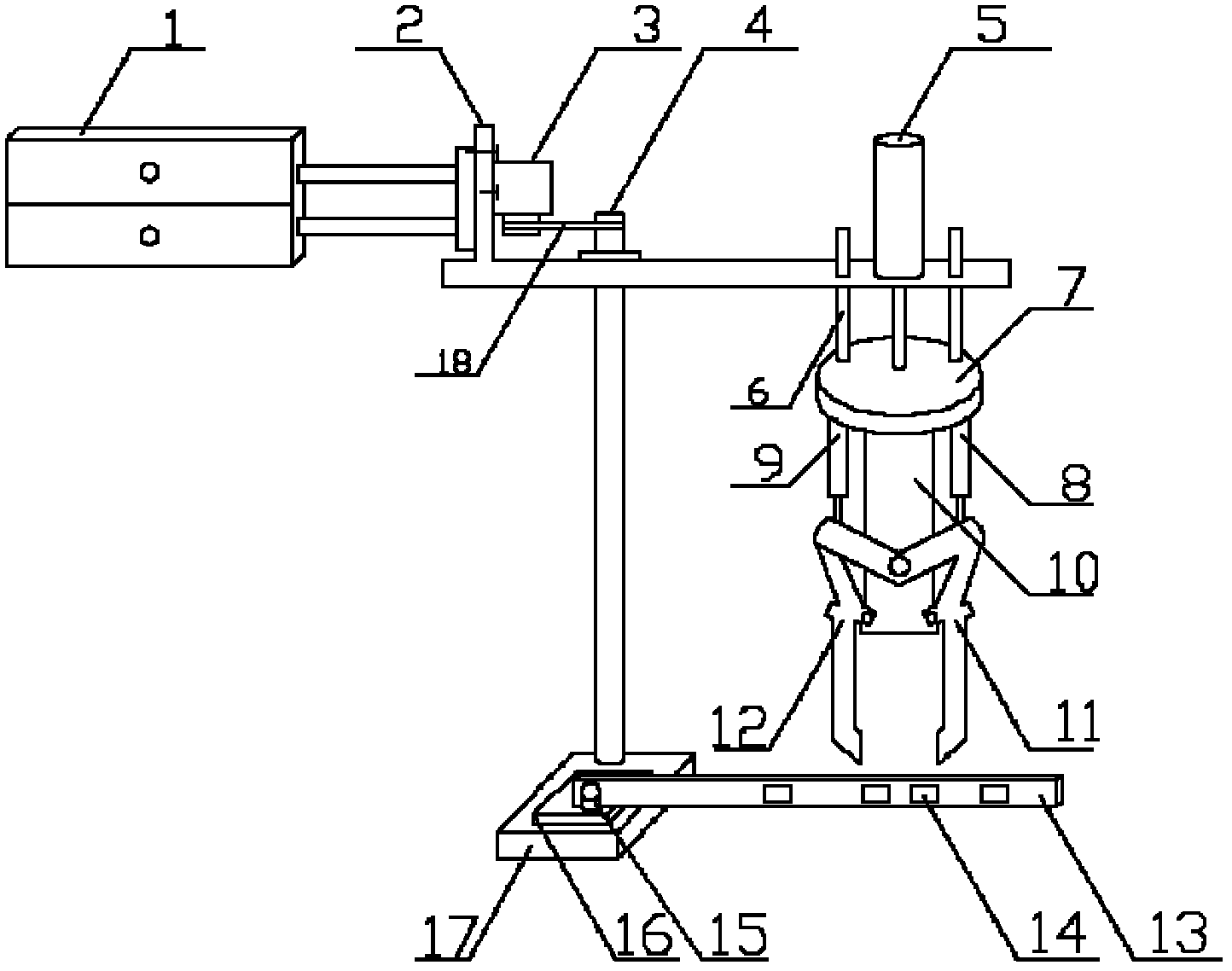
[0015] Such as figure 1 As shown, the base 17 is fixed when the present invention is in use, the base 17 is provided with a boss 16, the laser ranging sensor 15 on the boss 16 and the pressure strain gauge 14 on the beam 13 sense the workpiece on the production line, and the stepping motor 3 The rotating shaft 4 is driven by the conveyor belt 18 to rotate the fixed plate 2, the air cylinder I1 telescopically adjusts the position, the air cylinder II5 telescopically drives the fixed table 7 and the support column 6 to move, and the air cylinder III8 and the air cylinder IV9 drive the right finger connected to the support plate 10 11 and 12 left fingers to achieve tightening and relaxation.

[0016] Although the specific implementation of the present invention has been described above in conjunction with the accompanying drawings, it does not limit the p...


PUM


Abstract

The invention discloses a pneumatic manipulator which comprises a base, a rotating shaft, a fixed plate, a rotating mechanism and a claw mechanism, wherein one end of the rotating shaft is connected with the base, and the other end of the rotating shaft is connected with the fixed plate; the fixed plate is L-shaped, the L end is connected with the rotating mechanism, and the other end is connected with the claw mechanism; a stepper motor on the rotating mechanism is connected with the rotating shaft through a conveyor belt; the claw mechanism comprises a pneumatic cylinder II, a plurality of support columns, a fixed table, a pneumatic cylinder III, a pneumatic cylinder IV, a support plate, a left finger and a right finger; a telescopic shaft of a hydraulic cylinder II and the support columns penetrate through holes on the fixed plate and are connected with the upper end surface of the fixed table, and the lower end surface of the fixed table is connected with the support plate, a hydraulic cylinder III and a cylinder body of a hydraulic cylinder IV; and the left finger and the right finger are respectively connected with the lower end of the support plate, the right finger is connected with a telescopic shaft of the pneumatic cylinder III, and the right finger is connected with a telescopic shaft of the pneumatic cylinder IV. The invention has the advantages of simple debugging, convenience for installation and use, reliable performance and high production efficiency and realizes mechanical automation.

Description

technical field [0001] The invention relates to a manipulator, in particular to a pneumatic manipulator. Background technique [0002] Manipulators are very commonly used clamping equipment for mechanical production, but when processing special shapes, it is not easy to determine where the manipulator clamps the workpiece each time, and the clamping is not easy to control, which affects production efficiency and products. Contents of the invention [0003] The object of the present invention is to solve the above problems and provide a pneumatic manipulator, which has the advantages of simple debugging, convenient installation, reliable performance and high production efficiency. [0004] In order to achieve the above object, the present invention adopts the following technical solutions: [0005] A pneumatic manipulator, including a base, a rotating shaft, a fixed plate, a rotating mechanism and a claw mechanism. One end of the rotating shaft is connected to the base, an...

Claims


Application Information

Patent Timeline
Patent Type & Authority Applications(China)
IPC IPC(8): B25J15/08B25J19/02
Inventor 申超姜晓利董旭李阳阳刘华侠王文波姜胜磊仲富惟王文东杜志元曹学友
Owner 申超
Why Eureka
Try Eureka