Air intake and exhaust thermal control device and method for implementing HCCI (homogeneous charge compression ignition) combustion of gasoline engine

A thermal control, air intake and exhaust technology, applied in the direction of fuel heat treatment devices, exhaust devices, electrical control, etc., can solve the problems of airflow resistance increase, size increase, heat exchanger difficult to greatly improve heat exchange efficiency, etc., to achieve Reduce demand, rationally store or release, and achieve the effect of selective and appropriate utilization

Active Publication Date: 2012-02-22
TIANJIN UNIV
6 Cites 9 Cited by

AI-Extracted Technical Summary

Problems solved by technology

However, the gas-air heat exchanger itself has the disadvantage of low heat transfer efficiency. It is difficult to optimize the structural parameters of the heat exchanger to greatly improve its heat transfer efficiency. At the same time, ...

Abstract

The invention discloses an air intake and exhaust thermal control system for implementing HCCI (homogeneous charge compression ignition) combustion of a gasoline engine. The system comprises an air intake pipeline, an air exhaust pipeline and an air exhaust-intake heat exchanger, wherein the heat exchanger is filled with heat storage materials; the air intake pipeline, the air exhaust pipeline and a bypass are respectively provided with an electrically operated valve; the pipelines are provided with a plurality of temperature sensors; the electrically operated valves and the temperature sensors are connected with a controller; and the controller comprises a signal conditioning circuit and a driving circuit which are connected with a singlechip and are used for implementing the thermal control of air intake and air exhaust. The device provided by the invention has the heat storage capability of the heat exchanger, reasonable storage and release of air exhaust heat can be realized. Whenthe gasoline engine operates at medium and large load, the storage and accumulation of surplus air exhaust heat in the heat exchanger can be realized, and the device is used for heating the intake air when the gasoline engine operates at low load, the problem that the air exhaust heat is insufficient to heat the intake air at low load is solved, the requirement of air exhaust-intake heat exchangeefficiency is lowered, and the device can be practically applied to the HCCI combustion of the gasoline engine.

Application Domain

Electrical controlInternal combustion piston engines +3

Technology Topic

Hcci combustionEngineering +10

Image

  • Air intake and exhaust thermal control device and method for implementing HCCI (homogeneous charge compression ignition) combustion of gasoline engine
  • Air intake and exhaust thermal control device and method for implementing HCCI (homogeneous charge compression ignition) combustion of gasoline engine
  • Air intake and exhaust thermal control device and method for implementing HCCI (homogeneous charge compression ignition) combustion of gasoline engine

Examples

  • Experimental program(1)

Example Embodiment

[0025] The present invention will be further described in detail below in combination with specific embodiments.
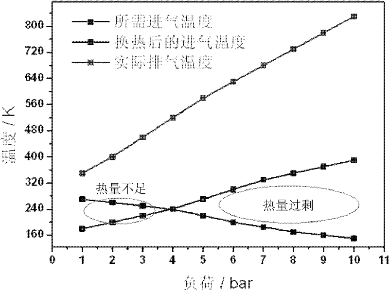
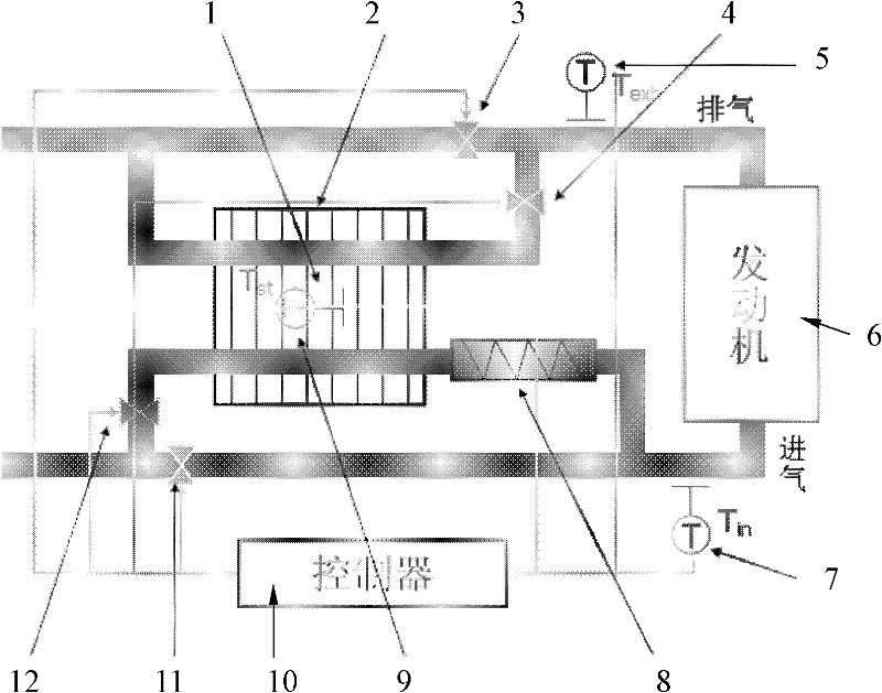
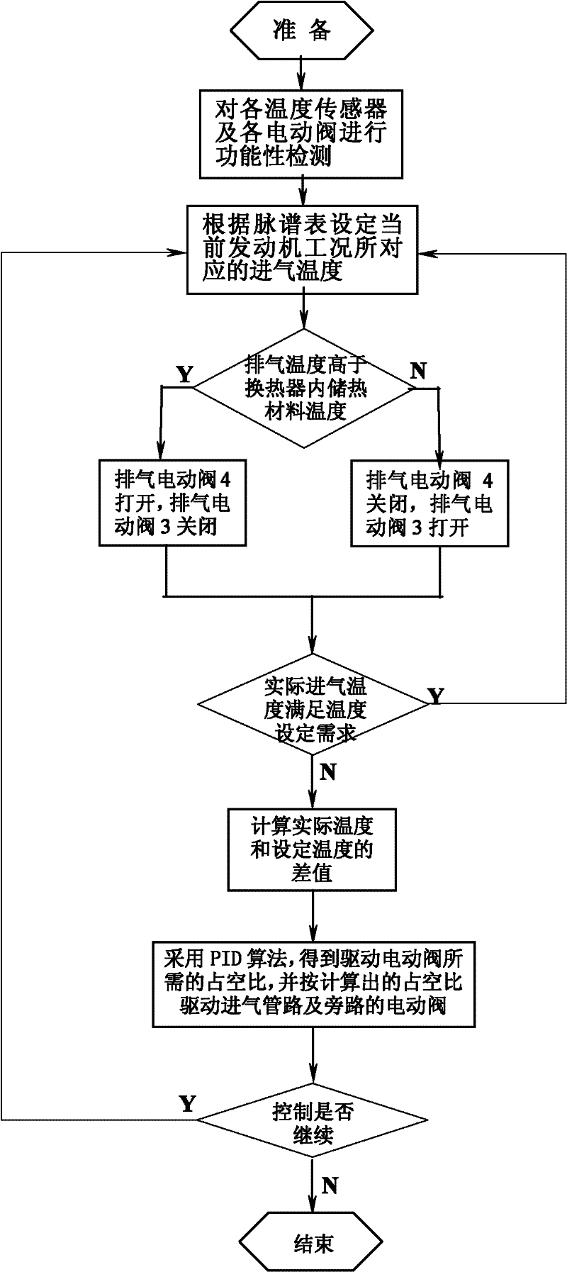
[0026] The basic idea of ​​the present invention is to use an exhaust-intake heat exchanger containing heat storage materials, and to install electric valves on the exhaust and intake pipes, and realize the heat transfer in the exhaust by opening and closing the electric valves of the exhaust pipes. Accumulation and storage in the heat exchanger, at the same time, through the adjustment of the opening of the intake pipeline and the bypass electric valve, the intake air can use the heat in the heat exchanger in an appropriate amount.
[0027] like figure 2As shown, the present invention realizes the intake and exhaust heat control device of gasoline engine HCCI combustion, including an exhaust pipeline, an intake pipeline and an exhaust-intake heat exchanger 2, and the exhaust pipeline is provided with a The exhaust bypass of the air-intake heat exchanger, the intake pipeline is provided with an intake bypass through the exhaust-intake heat exchanger; the exhaust-intake heat exchanger 2 Filled with heat storage material 1, the heat storage material 1 can use high temperature resistant sensible heat heat storage material, because the phase change heat storage material can achieve a higher heat storage density, in order to make the exhaust-intake heat exchanger 2 The volume of the heat storage material 1 is relatively small, and the heat storage material 1 is preferably a solid-liquid phase change heat storage material with a phase transition temperature of 400 to 700 degrees. For example, a phase change heat storage material such as Al-Si alloy can be used. The exhaust pipeline, the exhaust bypass, the intake pipeline and the intake bypass are respectively provided with an electric valve; the exhaust pipeline is located upstream of the exhaust bypass An exhaust gas temperature sensor 5 is provided at the intake pipe, an intake air temperature sensor 7 is provided on the intake pipeline and downstream of the intake bypass, and a heat exchange sensor 7 is installed in the exhaust-intake heat exchanger 2 The internal temperature sensor 9 of the device; the above-mentioned electric valves 3, 4, 11, 12 and the exhaust temperature sensor 5, the intake air temperature sensor 7 and the internal temperature sensor 9 of the heat exchanger are all connected to a controller 10; the controller 10 It includes a signal conditioning circuit and a driving circuit connected to a single-chip microcomputer, and the single-chip microcomputer can adopt Infineon's TC1766/TC1793. For the selection of the single-chip microcomputer in the controller, the composition of the signal conditioning circuit and the driving circuit, and the relationship between the three The connection relationship of all belongs to the common knowledge known to those skilled in the art, and will not be repeated here. Wherein, the signal conditioning circuit is connected with the exhaust gas temperature sensor 5, the intake air temperature sensor 7 and the internal temperature sensor 9 of the heat exchanger, and the signal conditioning circuit is used for processing the temperature sensor signal; the driving circuit is connected with the The above-mentioned electric valves are connected, and the drive circuit is used to realize the driving of each electric valve; the single-chip microcomputer is used for data calculation and logic judgment, that is, the single-chip microcomputer is used for the above-mentioned electric valves according to the processing results obtained from the signal conditioning circuit. The opening and closing of the valve and the opening state are adjusted to realize the thermal control of the intake and exhaust.
[0028] In addition, for the extreme situation that may occur, that is, the engine works under low load conditions for a long time so that the exhaust heat in the heat exchanger is insufficient, it can be located on the intake bypass road and located in the exhaust-intake exchange The downstream of the heater 2 is provided with an intake electric heater 8 . Its main purpose is to turn on the intake electric heater 8 at this moment in order to make the intake air temperature of the engine meet the demand of HCCI combustion under the current working condition when the heat provided by the heat storage heat exchanger is insufficient, and the intake air after heat exchange Carry out heating again to make it meet the intake air temperature requirement of HCCI combustion.
[0029] like image 3 As shown, the control method using the above-mentioned intake and exhaust heat control device for realizing HCCI combustion of a gasoline engine includes the following steps. Here, a single-cylinder gasoline engine is taken as an example to specifically describe the intake and exhaust heat control:
[0030] Step 1. Perform functional testing on each temperature sensor and each electric valve;
[0031] Step 2. Set the intake air temperature corresponding to the current engine working condition according to the map table. For example, if the current engine is working at a load whose IMEP is 4bar, check the table and know that the intake air temperature required for the current engine working condition is 230°C;
[0032] Step 3: The signal conditioning circuit obtains the temperature at the upstream position of the exhaust pipeline through the exhaust temperature sensor 5, and it can be known that the exhaust temperature is 400°C, and at this time the temperature acquired by the heat storage internal temperature sensor 9 of the heat exchanger is 350°C , the single-chip microcomputer judges that at this time the exhaust gas temperature is higher than the temperature of the heat storage material 1 in the exhaust-intake heat exchanger 2, then the single-chip microcomputer sends a signal to the drive circuit to open the electric valve on the exhaust bypass and close the said exhaust bypass at the same time. The command of the electric valve on the exhaust pipeline makes the engine exhaust flow through the exhaust-intake heat exchanger, so that the exhaust heat is accumulated and stored in the heat exchanger;
[0033] Step 4: The signal conditioning circuit obtains the actual temperature at the downstream position of the intake pipe through the intake air temperature sensor 7 as 220°C. The single-chip microcomputer judges that the actual temperature does not meet the set value of the intake air temperature of 230°C, and calculates the actual temperature and The difference between the set values ​​is -10°C, and then use the PID algorithm to obtain the duty ratio required to drive the electric valve of the intake pipeline and the intake bypass, and then the drive circuit drives the intake pipeline according to the above duty ratio. The action of the electric valve and the electric valve of the intake bypass makes the opening of the electric valve of the intake bypass increase appropriately and the opening of the electric valve of the intake pipeline decrease appropriately, so that the actual temperature tends to the set value of the intake air temperature;
[0034] Step 5: Judging whether the system performs the next thermal control cycle, if "yes", return to the above step 2, and continue the thermal control, otherwise, end the thermal control.
[0035] Although the present invention has been described above in conjunction with the drawings, the present invention is not limited to the above-mentioned specific embodiments, and the above-mentioned specific embodiments are only illustrative rather than restrictive. Under the inspiration, many modifications can be made without departing from the gist of the present invention, and these all belong to the protection of the present invention.

PUM

PropertyMeasurementUnit
Phase transition temperature400.0 ~ 700.0deg

Description & Claims & Application Information

We can also present the details of the Description, Claims and Application information to help users get a comprehensive understanding of the technical details of the patent, such as background art, summary of invention, brief description of drawings, description of embodiments, and other original content. On the other hand, users can also determine the specific scope of protection of the technology through the list of claims; as well as understand the changes in the life cycle of the technology with the presentation of the patent timeline. Login to view more.

Similar technology patents

Continuous foaming aluminum automatic production line

Owner:CHANGXING CAZENOVE FUNANCE IND CO LTD

Binding process evaluation method and device, server and storage medium

PendingCN112036666AData is accurate and objectivereduce demand
Owner:CHINA MOBILEHANGZHOUINFORMATION TECH CO LTD +1

Anaerobic ammonia oxidation-couped denitrification composite denitrification system and quick starting method

PendingCN110436626AImprove denitrification effectreduce demand
Owner:XI'AN UNIVERSITY OF ARCHITECTURE AND TECHNOLOGY

Medical procedure simulator

InactiveCN106575486Areduce demand
Owner:MOOG INC
Why Eureka
Try Eureka