Thread lock

A technology of thread lock and lock shell, applied in the direction of threaded fasteners, screws, nuts, etc., can solve the problems of flying out of the bottom plate or skirt plate, disappearance of pre-tightening force, loosening of T-shaped screw 101, etc., so as to achieve easy maintenance and replacement. , the effect of preventing loosening

Active Publication Date: 2012-02-22
CRRC TANGSHAN CO LTD +1
View PDF4 Cites 0 Cited by
  • Summary
  • Abstract
  • Description
  • Claims
  • Application Information

AI Technical Summary

Problems solved by technology

[0003] However, when a high-speed train is running at high speed and passing through caves and bridges, the floor or skirt will generate strong positive and negative pressures and strong vibrations due to airflow changes, which may cause T-shaped The screw 101 rotates left and right so that the pre-tightening force applied to the T-shaped screw 101 is lower than the critical value, which in turn causes the pre-tightening force to disappear rapidly, causing the T-shaped screw 101 to loosen or even fall off. Flying out when the train is running at high speed, causing great hidden danger to driving safety

Method used


Image

  • Thread lock
  • Thread lock
  • Thread lock

Examples


Embodiment 1

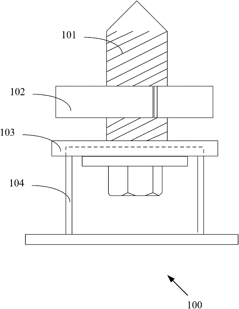
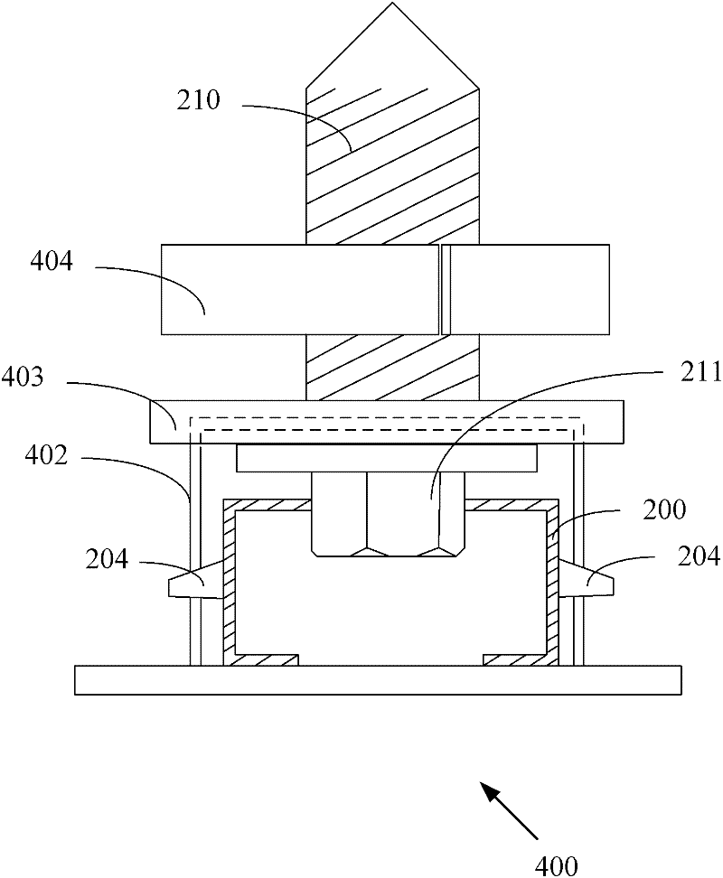
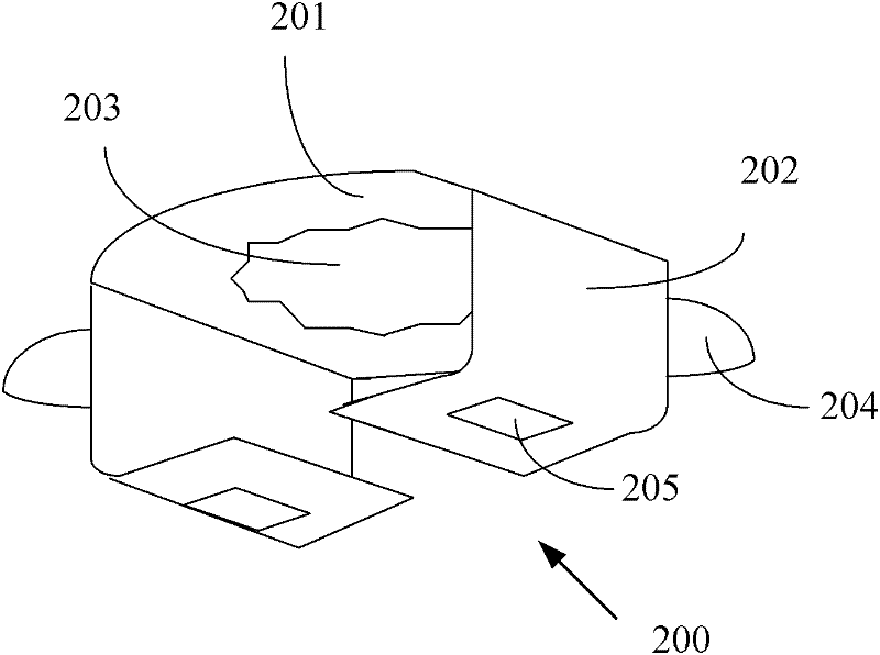
[0032] like Figure 2A Shown is a schematic structural view of the thread lock according to the first embodiment. The thread lock 400 comprises: a screw 210 with a polygonal head 211, a lock case 402, a locking part 403, and a nut 404, and the screw 210 passes through the lock case 402, the locking part 403 and the nut 404 in turn, so that the polygonal head 211 is positioned at Inside the lock case 402 , at least one locking slot (not shown in the figure) is provided on the side wall of the lock case 402 , and the lock case 402 is also provided with a holding part 200 . combine Figure 2B As shown, the clamping component 200 has a top plate 201 and at least one side plate 202 connected to the top plate 201 . A non-return hole 203 is opened on the top plate 201, and the non-return hole 203 is used to clamp the polygonal head 211. There is at least one protrusion 204 on the side plate 202, and the protrusion 204 is located in the slot, and slides and fits with the slot. When...

Embodiment 2

[0040] The second embodiment further improves the thread lock of the first embodiment. like Figure 4 As shown, it is an exploded view of the thread lock 500 according to the second embodiment, which shows the locking groove 410 on the lock case 402 . like Figure 5 As shown, it is a schematic structural diagram of the thread lock 500 according to the second embodiment. The thread lock 500 also includes a flat washer 501 and a wave washer 502 sleeved on the screw rod 210 , the flat washer 501 and the wave washer 502 are located in the lock housing 402 , and the flat washer 501 is located above the wave washer 502 . Other structures are consistent with those in Embodiment 1.

[0041] According to the thread lock 500 of the second example, the flat washer 501 and the wave washer 502 can increase the pre-tightening force of the screw 210 and the nut 404 through the deformation and friction caused by the screw 210, and improve the ability to prevent loosening and loosening.

...

Embodiment 3

[0045] like Figure 6A As shown, it is a schematic view viewed from the R-R direction of the thread lock 500 of the second embodiment. The clamping part 200 and the lock case 402 are respectively provided with looseness identification marks 601A and 601B. When the screw 210 is tightened, the looseness identification mark 601A of the clamping part 200 and the looseness identification mark 601B of the lock case 402 are located on the same straight line.

[0046] When the screw 210 rotates, that is, when the screw 210 becomes loose, the clamping part 200 will rotate in the lock housing 402. At this time, the loose identification marks 601A and 601B are no longer located on the same straight line, such as Figure 6B shown. At this time, the staff can judge whether the screw rod 210 is loose according to the states of 601A and 601B, and can carry out inspection and maintenance in time to further ensure the tight connection between the bottom plate and the vehicle body.

[0047] T...


PUM


Abstract

The invention discloses a thread lock. The thread lock comprises a lock shell, a locking part, a nut and a screw with a polygonal head, wherein the screw passes through the lock shell and the locking part in turn and is connected with the nut in a matched mode; and the polygonal head is positioned in the lock shell. The thread lock is characterized in that: the side wall of the lock shell is provided with at least one clamping groove; a clamping part is arranged in the lock shell and comprises a top plate and at least one side plate; the top plate is provided with a non-return hole for clamping the polygonal head; the at least one side plate is connected with the top plate; each side plate is provided with at least one bulge; each bulge is positioned in each clamping groove; and when the screw rotates, each bulge is driven to slide along each clamping groove. According to the thread block, the screw can be prevented from loosening and even falling; and the thread lock is easy to maintain and replace, and the conventional thread lock is not excessively changed, so the thread lock can be applied to various conventional vehicle bodies, and excessive cost is not increased.

Description

technical field [0001] The invention relates to railway safety technology, in particular to a threaded lock. Background technique [0002] On high-speed trains, T-shaped thread locks are generally used for the fixed connection of the bottom floor of the high-speed EMU, the skirts on both sides and the car body. like figure 1 Shown is the structural representation of the existing T-shaped thread lock. The structure of the T-shaped screw lock 100 is a T-shaped screw 101 , a nut 102 , a locking component 103 and a lock case 104 from top to bottom. In the prior art, the nut 102 is generally fixed on the car body first, the lock housing 104 is fixed on the base plate or skirt of the high-speed EMU through the locking member 103, and then the T-shaped screw 101 is passed through the lock housing 104 to align The nut 102 continuously rotates the T-shaped screw rod 101 until the specified torque is reached, and the bottom plate or skirt plate is fixed on the vehicle body. [000...

Claims


Application Information

Patent Timeline
Patent Type & Authority Applications(China)
IPC IPC(8): F16B39/10
Inventor 马纪军王立航范乐天陈亮
Owner CRRC TANGSHAN CO LTD
Why Eureka
Try Eureka