Cavity filter, communication equipment and low pass filter

A cavity filter and cavity technology, applied in the field of communication, can solve problems such as difficult assembly, achieve the effects of improved pass rate and assembly efficiency, reduced assembly contact surface, and high pass rate

Inactive Publication Date: 2012-02-22
ANHUI TATFOOK TECH CO LTD
View PDF5 Cites 3 Cited by
  • Summary
  • Abstract
  • Description
  • Claims
  • Application Information

AI Technical Summary

Problems solved by technology

[0009] The invention provides a cavity filter and communication equipment including the cavity filter, which can solve the problem of difficult assembly between the low-pass body structure and the cavity hole in the cavity filter

Method used


Image

  • Cavity filter, communication equipment and low pass filter
  • Cavity filter, communication equipment and low pass filter
  • Cavity filter, communication equipment and low pass filter

Examples


Embodiment 1

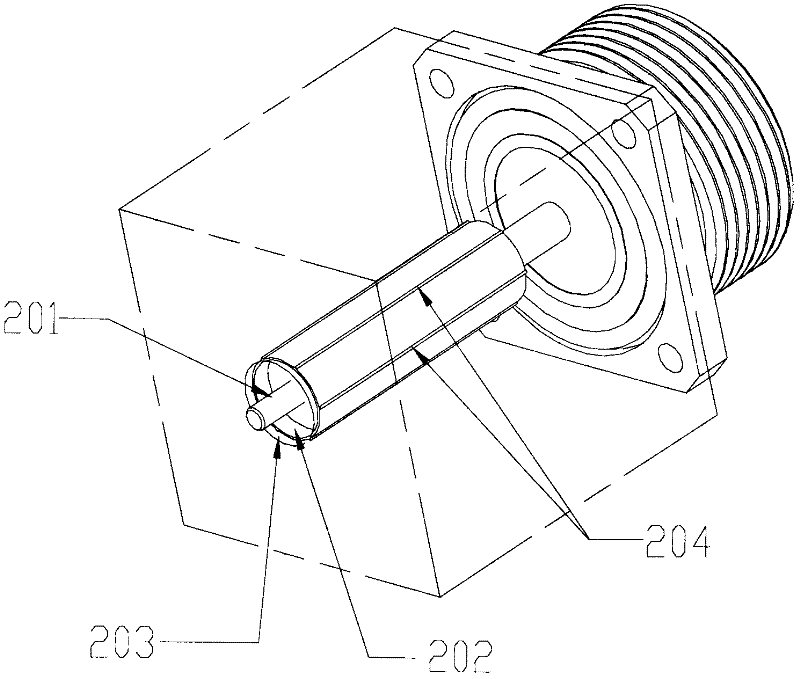
[0028] Embodiment 1. A cavity filter, such as image 3 and image 3 Sectional view of Figure 4 As shown, it includes a cavity hole 203 and a low-through structure 201 pierced through the cavity hole 203. An insulating dielectric sleeve 202 is arranged between the low-through body structure 201 and the cavity hole 203. The insulating dielectric sleeve 202 is connected to the The cavity hole 203 is an interference fit, and the outer surface of the insulating dielectric sleeve 202 is provided with a protrusion 204 .

[0029] The outer surface of the insulating medium cover 202 is provided with a protrusion 204, and the protrusion 204 is in direct contact with the cavity hole 203, thus reducing the mating contact surface between the insulating medium cover 202 and the cavity hole 203 , which can increase the amount of fit interference and reduce the possibility of clearance fit, so as to achieve the relative position stability of the low-through body structure 201, so as to ach...

Embodiment 2

[0038] Embodiment 2, a cavity filter, such as Figure 5 As shown, it includes a cavity hole 303 and a low-pass body structure 301 pierced through the cavity hole 303. An insulating dielectric sleeve 302 is arranged between the low-pass body structure 301 and the cavity hole 303. The insulating dielectric sleeve 302 and the The cavity hole 303 is an interference fit, and the outer surface of the insulating dielectric sleeve 302 is provided with a protrusion 304 .

[0039]The outer surface of the insulating medium cover 302 is provided with a protrusion 304, and the protrusion 304 is in direct contact with the cavity hole 303, thus reducing the mating contact surface between the insulating medium cover 302 and the cavity hole 303 , which can increase the amount of fit interference and reduce the possibility of clearance fit, so as to achieve the relative position stability of the low-through body structure 301, so as to achieve stable and reliable index data of the cavity filter...

Embodiment 3

[0050] Embodiment 3. A cavity filter, as shown in 6, includes a cavity hole 403 and a low-pass body structure 401 pierced through the cavity hole 403, and the low-pass structure 401 and the cavity hole 403 are provided with An insulating dielectric sleeve 402 , the insulating dielectric sleeve 402 is in interference fit with the cavity hole 403 , and a protrusion 404 is provided on the outer surface of the insulating dielectric sleeve 402 .

[0051] The outer surface of the insulating medium cover 402 is provided with a protrusion 404, and the protrusion 404 is in direct contact with the cavity hole 403, thus reducing the mating contact surface between the insulating medium cover 402 and the cavity hole 403 , which can increase the amount of fit interference and reduce the possibility of clearance fit, so as to achieve the relative position stability of the low-through body structure 401, so as to achieve stable and reliable index data of the cavity filter; because the insulati...


PUM


Abstract

The invention discloses a cavity filter. An insulated medium sleeve is arranged between a low whole body structure and a cavity hole; the insulated medium sleeve and the cavity hole are in an interference fit; and projections are arranged on the outer surface of the insulated medium sleeve. According to the cavity filter, the equipment and the low pass filter provided in the invention, projections are arranged on an outer surface of an insulated medium sleeve, so that a fit contact area between the insulated medium sleeve and a cavity hole is reduced; therefore, on the hand, a fit interference magnitude can be enlarged and the possibility of a clearance fit is reduced, so that stability of a relative position of a whole body structure can be realized; on the other hand, a frictional force between the insulated medium sleeve and the cavity hole can be reduced, so that the whole body structure can be protected from being damaged.

Description

technical field [0001] The invention relates to the communication field, in particular to a cavity filter, a communication device using the cavity filter and a low-pass filter. Background technique [0002] As a frequency selective device, cavity filters are widely used in the field of communication, especially in the field of radio frequency communication. In the base station, the cavity filter is used to select the communication signal and filter out the clutter or interference signal outside the frequency of the communication signal. [0003] In order to meet the filtering requirements of the cavity filter, some cavity filters are also equipped with a low-pass filter. The low-pass filter allows low-frequency signals to pass, but attenuates signals with a frequency higher than the cut-off frequency. Such as figure 1 and figure 2 As shown, the low-pass filter generally used in the cavity filter includes a low-pass structure 101 composed of a core conductor and a plurali...

Claims


Application Information

Patent Timeline
Patent Type & Authority Applications(China)
IPC IPC(8): H01P1/20H01P1/207H04W88/08
Inventor 杨绍春
Owner ANHUI TATFOOK TECH CO LTD
Why Eureka
Try Eureka