Multi-stage rotary oil supply joint

A technology of oil supply and oil outlet, applied in the direction of pipe components, etc., can solve the problem of hydraulic system coordination time difference, etc., and achieve the effect of compact structure and convenient use of the device

Inactive Publication Date: 2012-02-29
CHANGZHOU TENT HYDRAULIC MACHINERY
View PDF5 Cites 5 Cited by
  • Summary
  • Abstract
  • Description
  • Claims
  • Application Information

AI Technical Summary

Problems solved by technology

[0003] The purpose of the present invention is to solve the problem of time difference in operation of the hydraulic system. It provides a multi-stage rotary oil supply joint, including a mandrel and an outer cylinder. ° rotation, a support bearing is provided between the mandrel and the outer cylinder, and a gland fixedly connected to the outer cylinder is provided at the rear of the mandrel and the outer cylinder, and the feature is that the mandrel includes a shaft oil inlet pipe and a shaft oil outlet The shaft oil inlet pipeline is provided with multiple shaft oil inlets, the shaft oil outlet pipeline is provided with multiple shaft oil outlets, the upper part of the outer cylinder is provided with multiple oil outlet holes, and the lower part is provided with multiple shaft oil outlets. oil inlet hole, the shaft oil inlet pipe is connected with the oil inlet hole, and the shaft oil outlet pipe is connected with the oil outlet hole to form an oil supply channel

Method used


Image

  • Multi-stage rotary oil supply joint
  • Multi-stage rotary oil supply joint
  • Multi-stage rotary oil supply joint

Examples


Embodiment Construction

[0008] Preferred embodiments of the present invention will be described in detail below in conjunction with the accompanying drawings.

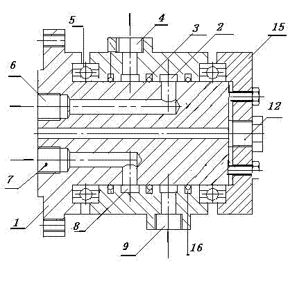
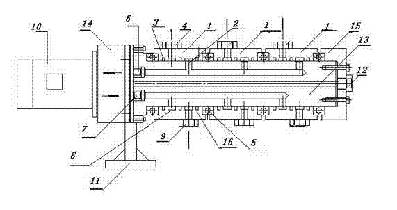
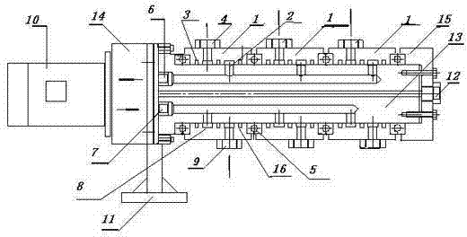
[0009] Such as figure 1 with figure 2 As shown, this embodiment provides a multi-stage rotary oil supply joint, including a mandrel 13 and an outer cylinder 1, the outer cylinder 1 is sleeved on the outside of the mandrel 13, the mandrel 13 can rotate 360° inside the outer cylinder 1, and the mandrel 13 and the outer cylinder 1 are provided with a support bearing 5, the mandrel 13 and the rear of the outer cylinder 1 are provided with a gland 15 fixedly connected with the outer cylinder 1, and the mandrel 13 includes a shaft oil inlet pipe 6 and a shaft oil outlet pipeline 7, the shaft oil inlet pipeline 6 is provided with a plurality of shaft oil inlets 2, the shaft oil outlet pipeline 7 is provided with a plurality of shaft oil outlets 8, and the upper part of the outer cylinder 1 is provided with a plurality of oil outlets Hole 4, the l...


PUM


Abstract

The invention provides a multi-stage rotary oil supply joint, which comprises a central spindle and an outer cylinder, wherein the outer cylinder is sleeved outside the central spindle; the central spindle can rotate 360 degrees in the outer cylinder; a support bearing is arranged between the central spindle and the outer cylinder; a gland fixedly connected with the outer cylinder is arranged on the rear parts of the central spindle and the outer cylinder; the central spindle comprises a spindle oil inlet pipeline and a spindle oil outlet pipeline; the spindle oil inlet pipeline is provided with a plurality of spindle oil inlets; the spindle oil outlet pipeline is provided with a plurality of spindle oil outlets; the upper part of the outer cylinder is provided with a plurality of oil outlets, and the lower part of the outer cylinder is provided with a plurality of oil inlets; and the spindle oil inlet pipeline is communicated with the oil inlets, and the spindle oil outlet pipeline is communicated with the oil outlets to form oil supply channels. The multi-pass rotary oil supply joint has the advantages that: an oil circuit of the central spindle and an oil circuit of the outer cylinder are matched to form a multi-stage oil circuit channel, so that the joint has a multi-path oil supplying capacity; and the whole device is compact in structure and convenient to use.

Description

technical field [0001] The invention relates to an oil supply joint of a hydraulic cylinder, in particular to a multi-stage rotary oil supply joint. Background technique [0002] At present, the application of hydraulic systems in large-scale machinery and equipment is becoming more and more common. In order to hydraulically control multiple actions, it often requires the cooperation of multiple hydraulic systems. Since the main actions of multiple hydraulic systems are carried out at the same time, a multi-head supply is required. oil equipment to control. Contents of the invention [0003] The purpose of the present invention is to solve the problem of time difference in operation of the hydraulic system. It provides a multi-stage rotary oil supply joint, including a mandrel and an outer cylinder. ° rotation, a support bearing is provided between the mandrel and the outer cylinder, and a gland fixedly connected to the outer cylinder is provided at the rear of the mandre...

Claims


Application Information

Patent Timeline
Patent Type & Authority Applications(China)
IPC IPC(8): F16L39/06
Inventor 陈益许一卫苏纯章志荣
Owner CHANGZHOU TENT HYDRAULIC MACHINERY
Why Eureka
Try Eureka