Method for inhibiting back cavitation of blade of mixed-flow water turbine

A technology of the back of the blade and the water turbine, which is used in the testing of machine/structural components, fluid dynamics testing, special data processing applications, etc.

Active Publication Date: 2012-02-29
HARBIN ELECTRIC MASCH CO LTD
View PDF4 Cites 12 Cited by
  • Summary
  • Abstract
  • Description
  • Claims
  • Application Information

AI Technical Summary

Problems solved by technology

[0012] Among the above methods, the cavitation performance of a pair of existing runners cannot be changed, the second method requires the installation of an air supply device, and the third method is difficult to

Method used


Image

  • Method for inhibiting back cavitation of blade of mixed-flow water turbine
  • Method for inhibiting back cavitation of blade of mixed-flow water turbine
  • Method for inhibiting back cavitation of blade of mixed-flow water turbine

Examples


Embodiment Construction

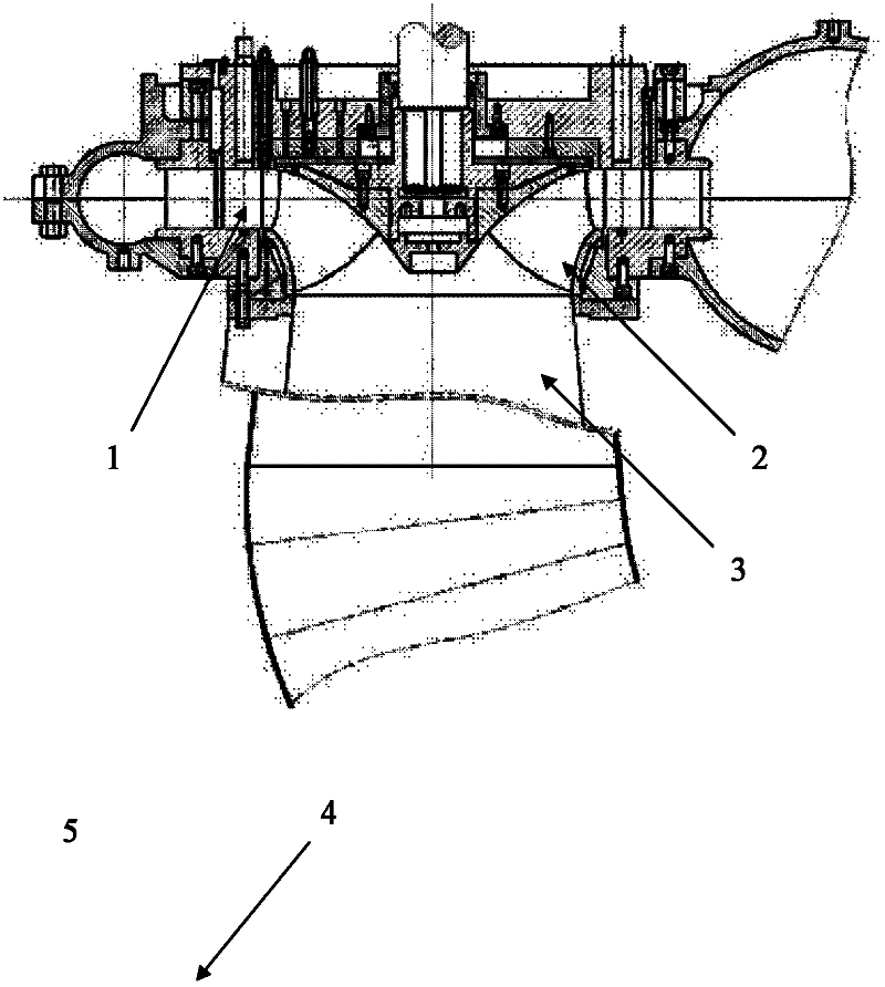
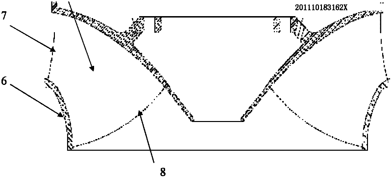
[0037] Such as image 3 As shown, the upper crown of the water turbine is 4, the blades of the water turbine are 5, the lower ring of the water turbine is 6, the water inlet edge of the water turbine blade is 7, and the water outlet edge of the water turbine blade is 8, Figure 4 It is a top view of the water turbine blade, the water turbine blade water inlet edge 7, the water turbine blade working surface 9, the water turbine blade back side 10, and the water turbine blade water outlet edge 8. During the operation of the Francis turbine, the water flow from image 3 The water inlet side shown enters the water turbine, flows through the blade area of ​​the water turbine, does work on the front of the water turbine blade, and finally flows out from the water outlet side. Since the water flow does work on the front of the blade, the pressure of the water flow on the front of the blade is relatively high. Figure 5 It is the pressure distribution diagram on the back of the blad...


PUM


Abstract

The invention relates to a method for inhibiting back cavitation of a blade of a mixed-flow water turbine. Pressure distribution analysis is carried out for calculation results, the location of the point with the lowest pressure on the back face of the blade can be obtained, that is, the point most prone to cavitation can be obtained, a small hole with the diameter being 0.003D1 is drilled at the point with the lowest pressure on the back face of the blade, the front face and the back face of the blade are connected, and high-pressure water flow on the front face can be compensated into the low-pressure center of the back face due to pressure difference between the front face and the back face, so that the pressure on the back face cannot reach the environmental vapor pressure, and thus the cavitation can be undermined. By adopting the method, when the mixed-flow water turbine operates under all normal conditions in a power station, no cavitation can easily occur to the blades of the water turbine, and the safe and stable operation of the water turbine can be ensured.

Description

Technical field: [0001] The invention relates to a method for suppressing cavitation on the back side of blades of a Francis water turbine. Background technique: [0002] Cavitation is a liquid phenomenon. When the temperature of the liquid is constant and the pressure is reduced to a certain critical pressure, the liquid will vaporize or the air dissolved in the liquid will develop to form cavities. This phenomenon is called cavitation, which includes The whole process of acupoint birth, development and growth to collapse. The cavitation process can occur inside a liquid as well as at a solid boundary. When the cavitation on the solid boundary collapses, the shock pressure wave will be radiated from the collapse center, and when this high-frequency shock pressure wave acts on the solid side wall, it will damage the solid side wall, which is cavitation formed. [0003] The cavitation and cavitation erosion phenomena in hydraulic turbines are customarily defined according ...

Claims


Application Information

Patent Timeline
IPC IPC(8): G06F17/50G01M10/00
Inventor 刘万江许彬赵越韩秀丽李树伟史千赵昊阳
Owner HARBIN ELECTRIC MASCH CO LTD
Why Eureka
Try Eureka