Safe and automatic brake of wind power generator

A wind power generator, safe and automatic technology, applied in the direction of reduction gear parts, etc., can solve the problems of large power consumption, insufficient buffering, insufficient buffering, etc., and achieve the effect of saving power and sufficient buffering

Inactive Publication Date: 2013-04-17
ZHEJIANG FENGGUANG NEW ENERGY TECH
View PDF6 Cites 0 Cited by
  • Summary
  • Abstract
  • Description
  • Claims
  • Application Information

AI Technical Summary

Problems solved by technology

[0003]Application number: 201010120086.3, application publication number CN101794983A discloses a safety automatic braking device for wind-driven generators, and its disadvantages are: 1. "Under normal circumstances, The electromagnetic coil is always energized, and the disc-shaped armature and the upper friction plate and the lower friction plate that are connected to the annular armature to clamp the clutch connection plate are dragged and sucked” (see application number: 201010120086.3 patent document specification page 4 Paragraph 0014) to separate the clutch connection plate from the generator rotor
Its electromagnetic coil has been dragging the ring-shaped armature, so it consumes a lot of power during use. At the same time, the off-grid generator will cause power shortage when there is no power generation in the breeze, which will cause the brakes to fail to work. Once the power is cut off, it will automatically brake. , seriously affecting the safe and normal operation of wind power generation equipment
2. When it brakes, the upper friction disc and the lower friction disc clamp the clutch connecting disc to brake, and the buffer is insufficient during braking. In the case of strong typhoon, it is easy to use it to brake because the spring pressure is large during braking. Insufficient cushioning damages the rotor
The friction plate has been rubbed many times and the friction cannot be adjusted after being worn out. At the same time, when the wind turbine cannot generate electricity normally, it will consume the stored power of the wind turbine instead.

Method used


Image

  • Safe and automatic brake of wind power generator
  • Safe and automatic brake of wind power generator
  • Safe and automatic brake of wind power generator

Examples


Embodiment

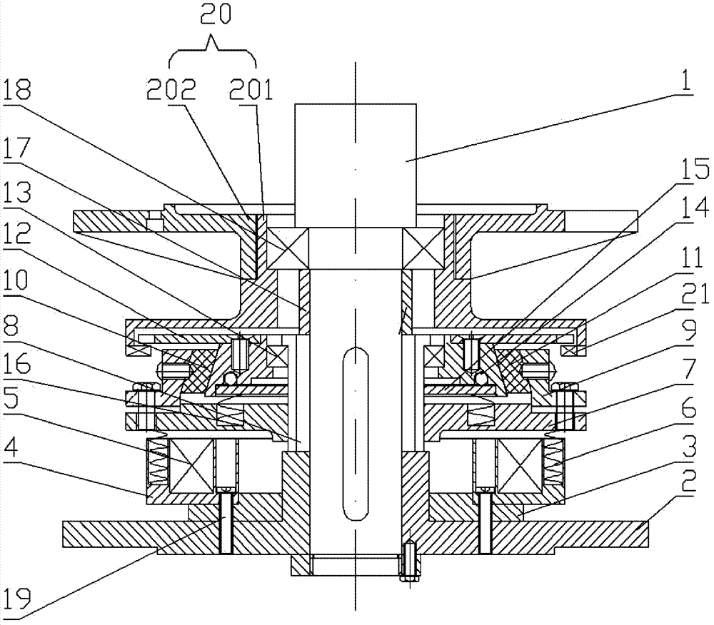
[0025] Example: see Figures 1 to 6 As shown, the safety automatic braking device for wind power generators includes a stator shaft 1 and a base 2, the stator shaft 1 is fixed on the base 2, an aluminum part 3 is fixed on the base 2, a magnetic base 4 is fixed on the aluminum part 3, and an electromagnetic coil 5 Fixed on the magnetic base 4, one end of the first spring 6 acts on the magnetic base 4, and the other end acts on the suspension iron 7;

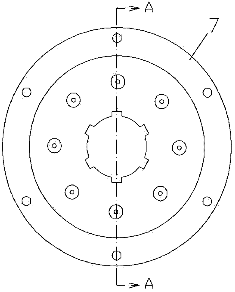
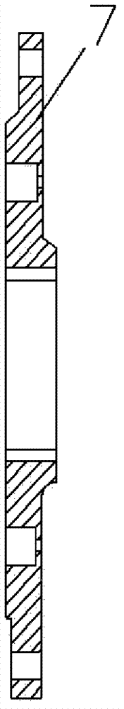
[0026] The annular suspension iron 7 is inserted on the spline sleeve 8, and the spline sleeve 8 is inserted on the stator shaft 1. The suspension iron 7 and the outer ring 9 are fixed together by screws, and the outer ring 9 is fixed on the conical shaft by screws. On the brake ring 10, the inner inclined ring surface 101 of the tapered brake ring 10 is pressed against the outer inclined ring surface 111 of the brake pad seat 11, the brake pad 12 is fixed on the brake pad seat 11 by screws, and the brake pad seat 11 is fixed on t...


PUM


Abstract

A safe and automatic brake of a wind power generator is disclosed. A stator shaft is fixed in a pedestal. An electromagnetic coil is fixed on a magnetic base. One end of a spring applies force on the magnetic base and the other end applies the force on a suspended iron. The annular suspended iron and a spline sleeve are sleeved on the stator shaft. A baffle ring is formed on the spline sleeve. Aninner ring of the suspended iron is located between the baffle ring and an upper part of the pedestal. The suspended iron is fixed with an outer ring through a screw. A locating ring is fixed on the outer ring through the screw and is sleeved on a ring slot of a rubber ring. An inner bevel of the rubber ring suppresses on a lower base of a blade. The inner ring of a bearing is fixed on the statorshaft. The outer ring of the bearing is fixed with the inner ring of the lower base of the blade. An upper base of the blade is fixed with the lower base of the blade. The upper base of the blade is sleeved on the lower base of the blade and presses on a step of the lower base of the blade. A sleeve is sleeved on the stator shaft. The upper part of the sleeve presses on the lower part of the inner ring of the bearing. The lower part of the sleeve presses on the spline sleeve. A wind wheel is fixed with the upper base of the blade.

Description

Technical field: [0001] The invention relates to the technical field of generators, and more specifically relates to an automatic braking device for a wind-driven generator. Background technique: [0002] The wind power generation device is in a natural environment, the wind speed changes frequently and in a large range, and the ambient temperature changes greatly. Therefore, the harsh environment often causes the generator to overspeed and overheat and cause failure. In order to ensure the long-term normal operation of the wind power generator, it must An overspeed and overheat protection device is installed on the generator. But at present, most of the overspeed protection devices of wind power generators adopt multiple instantaneous electric short-circuit braking devices. However, under the condition of strong wind, high speed of wind rotor and large rotational torque, sudden instantaneous electric short-circuit braking often damages the rotating wind blades and Connect ...

Claims


Application Information

Patent Timeline
Patent Type & Authority Patents(China)
IPC IPC(8): H02P3/04
Inventor 张金明胡振其
Owner ZHEJIANG FENGGUANG NEW ENERGY TECH
Why Eureka
Try Eureka