Arc extinguish chamber device for circuit breaker

A technology for arc extinguishing chambers and circuit breakers, which is applied to circuits, electrical components, and electrical switches. It can solve problems such as reduced arc ignition performance, increased carbonization area of ​​arcs, and inability to cut arcs, so as to improve breaking performance and technical solutions. Simple, good arc extinguishing performance

Inactive Publication Date: 2012-03-07
FORETECH ELEC APP JIANGSU CORP
View PDF6 Cites 9 Cited by
  • Summary
  • Abstract
  • Description
  • Claims
  • Application Information

AI Technical Summary

Problems solved by technology

[0003] In the existing above-mentioned arc extinguishing chamber device, the shape and size of the gaps at the bottom of the arc extinguishing grids 1 adjacent up and down are all the same (both are left-right symmetrical "bottle-shaped") " gap), during assembly, the arc extinguishing grids 1 are neatly arranged and overlapped, not staggered, so that the arc generated after the circuit breaker is broken cannot be effectively cut, resulting in a decrease in the arc extinguishing performance of the circuit breaker
In addition, in the existing arc extinguishing chamber device, the arc extinguishing grid 1 located at the top and responsible for arc striking lacks an effective arc striking position, so that the arc generated after the circuit breaker is broken cannot enter the arc extinguishing chamber quickly and effectively; at the same time, the two The side arc shield 2 has a large area, so the arc generated after the circuit breaker is broken will increase its carbonization area and reduce the arc striking performance, so the current structural scheme is difficult to effectively improve the breaking performance of the circuit breaker

Method used


Image

  • Arc extinguish chamber device for circuit breaker
  • Arc extinguish chamber device for circuit breaker
  • Arc extinguish chamber device for circuit breaker

Examples


Embodiment

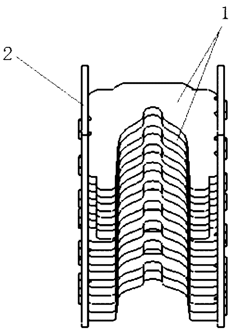
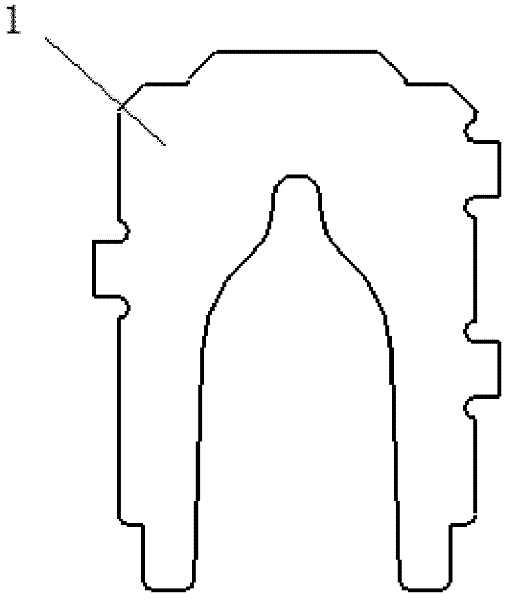
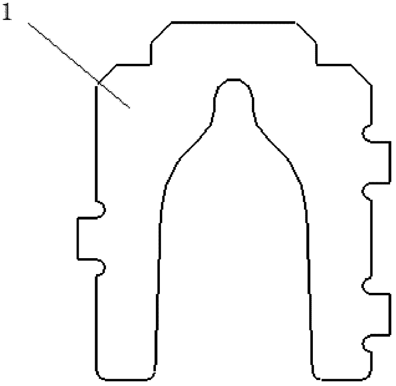
[0031] Example: first combine figure 1 , figure 2 , image 3 , Figure 4 As shown, it can be known that the existing circuit breaker arc extinguishing chamber device has the same shape and size of the gaps at the bottom of the arc extinguishing grid sheets 1 adjacent up and down (both are left-right symmetrical "bottle-shaped" gaps). When assembling, the arc extinguishing grid The sheets 1 are neatly arranged and overlapped, and are not staggered, so that the arc generated after the circuit breaker is broken cannot be effectively cut, resulting in a decrease in the arc extinguishing performance of the circuit breaker. In addition, in the existing arc extinguishing chamber device, the arc extinguishing grid 1 located at the top and responsible for arc striking lacks an effective arc striking position, so that the arc generated after the circuit breaker is broken cannot enter the arc extinguishing chamber quickly and effectively; at the same time, the two The side arc ...


PUM


Abstract

The invention discloses an arc extinguish chamber device for a circuit breaker, which comprises a plurality of arc extinction grids which are fixed between two flash barriers and arranged at intervals. A notch is arranged at the bottom of each arc extinction grid, wherein the arc extinction grid located at the uppermost end is a top arc extinction grid, and the arc extinction grids which are located below the top arc extinction grid are lower arc extinction grids. The arc extinguish chamber device is characterized in that: the notches at the bottoms of the adjacent lower arc extinction grids are symmetrical bilaterally in shape; and the notches at the bottoms of the adjacent lower arc extinction grids are alternatively stacked and arranged in a fish scale shape. The arc extinguish chamber device provided by the invention is simple in structure, has better arc extinction property and can be used for effectively improving the breaking ability of the circuit breaker.

Description

technical field [0001] The invention relates to an arc extinguishing chamber device for a circuit breaker. Background technique [0002] The arc extinguishing chamber device is a relatively important part in the arc extinguishing system of the circuit breaker. It is usually assembled with the arc extinguishing grid 1 and the arc shield 2 and then riveted and then assembled into the arc extinguishing chamber of the circuit breaker. . combine figure 1 , 2 , 3, and 4, it can be known that the current circuit breaker arc extinguishing chamber device, its arc extinguishing grid 1 ( figure 2 , image 3 ) with arc barrier 2 ( Figure 4 ) are fixed by riveting the protrusions on both sides of the arc extinguishing grid 1 with the corresponding positioning holes 2a on the arc shield 2 . [0003] In the existing above-mentioned arc extinguishing chamber device, the shape and size of the gaps at the bottom of the arc extinguishing grids 1 adjacent up and down are the same (both ...

Claims


Application Information

Patent Timeline
Patent Type & Authority Applications(China)
IPC IPC(8): H01H9/34
Inventor 杨海军曹兵兵
Owner FORETECH ELEC APP JIANGSU CORP
Why Eureka
Try Eureka