Deep drawing forming composite die for shallow conical pieces with sunken side walls

A compound mold and deep-drawing forming technology, which is applied in the direction of forming tools, manufacturing tools, metal processing equipment, etc., can solve problems such as difficult stretch forming of shallow conical parts, and achieve the effect of improving production efficiency and ensuring product quality

Active Publication Date: 2012-03-14
HARBIN JIANCHENG GRP
View PDF6 Cites 46 Cited by
  • Summary
  • Abstract
  • Description
  • Claims
  • Application Information

AI Technical Summary

Problems solved by technology

[0003] The purpose of the present invention is to provide a shallow conical part with concave side wall deep drawing composite mold to solve the problem that it is difficult to stretch and form the shallow conical part with concave side wall by using the existing mold

Method used


Image

  • Deep drawing forming composite die for shallow conical pieces with sunken side walls
  • Deep drawing forming composite die for shallow conical pieces with sunken side walls
  • Deep drawing forming composite die for shallow conical pieces with sunken side walls

Examples


specific Embodiment approach 1

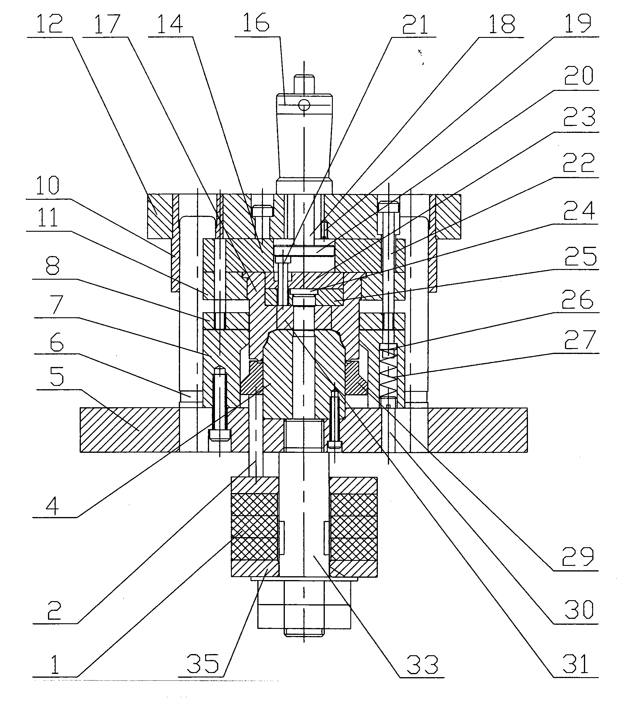
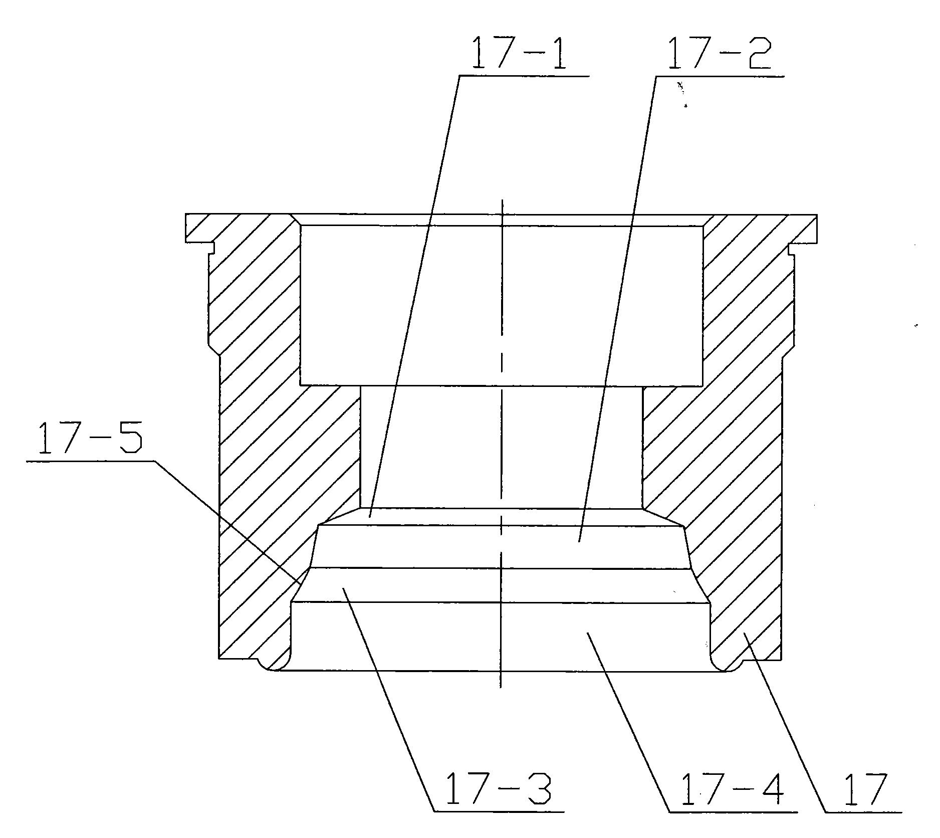
[0007] Specific implementation mode one: combine Figure 1-Figure 3 Illustrates that a composite die for deep-drawing of a shallow conical part with a concave side wall in this embodiment is composed of an upper die assembly and a lower die assembly; the upper die assembly includes a die handle 16, an upper die plate 12, two Guide sleeve 10, backing ring 14, fixed plate 11, punching rod 18, top plate 20, unloading connector 22, backing plate 23, punching punch 24, punching punch fixing plate 25, upper convex and concave die 17, return plate 31 and Threaded connector 21; lower mold assembly consists of support pin 2, lower template 5, two guide pillars 6, blanking die 7, discharge plate 8, lower convex die 4, retaining pin 26, blank holder ring 29, The spring 27, the support pin 2, the limit screw rod 30, the spiral tube 33, the supporting plate 35 and a group of edge-holding rubber pads 1 are composed; the lower end of the die handle 16 is detachably connected to the upper tem...

specific Embodiment approach 2

[0008] Specific implementation mode two: combination figure 1 Note that the upper mold assembly in this embodiment also includes anti-rotation locking screws 19 ; Others are the same as in the first embodiment.

Embodiment

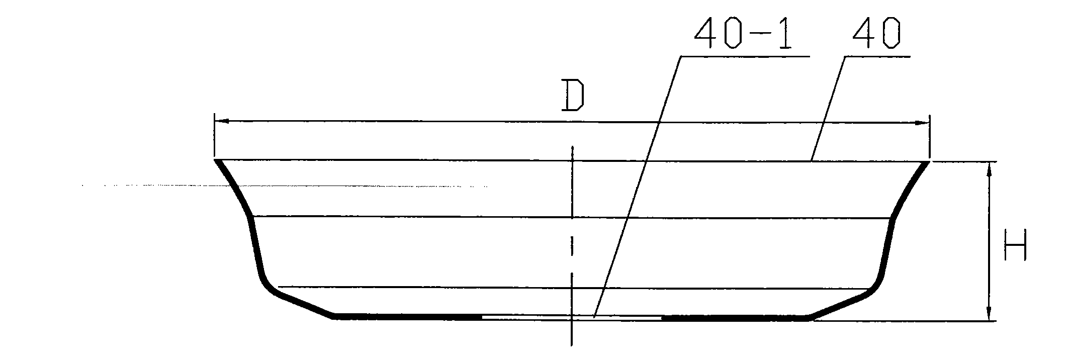
[0009] Embodiment: Utilize a shallow conical part with concave side wall of the present invention to draw and form a composite mold. After deep drawing, the outer diameter D at the port of the shallow conical part is 73.9 mm. The height H of the shape is 16.5mm.

[0010]The working principle is: according to the shape and size of the shallow conical part with the concave side wall that needs to be drawn, design the blanking die 7, the upper convex die 17, the lower convex die 4 and other auxiliary parts, and assemble them into a A complete composite mold. The composite mold is installed on the crank press, and the lower template 5 is fixed on the lower table of the crank press, and the upper mold assembly is fixed on the upper slide of the crank press (with the rotation of the crankshaft of the equipment, the same as the upper slide) The blocks move up and down together, and each reciprocating movement up and down once completes a working cycle. The downward movement is the w...


PUM


Abstract

The invention discloses a deep drawing forming composite die for shallow conical pieces with sunken side walls, and relates to a deep drawing forming composite die. The problem that the conventional die is difficult in forming the shallow conical pieces with the sunken side walls is solved. The upper end of a guide sleeve is in sliding fit with a guide post, and the lower end of the guide sleeve is in interference fit with a lower guide post hole of a lower template; a blanking female die is arranged on the lower template; an upper convex-concave die is connected with a fixed plate; a backingring is positioned between an upper template and the fixed plate; the upper convex-concave die is placed in the blanking female die; a spring and a baffle pin are arranged in circular bead through holes of the blanking female die; a limiting screw is arranged on the lower template; an ejection plate is arranged in the backing ring; a stripping rod is arranged on the backing ring; a punching male die fixed plate and a shim plate are arranged in the upper convex-concave die; a punching male die is arranged in a lower convex-concave die; the lower convex-concave die is arranged in a profile holeof the upper convex-concave die; a return plate is sleeved on the punching male die; a blank holder is sleeved on the lower convex-concave die; and a side pressing rubber pad and a supporting plate are sleeved on a solenoid. The die is used for deep drawing forming of the shallow conical pieces with the sunken side walls.

Description

technical field [0001] The invention relates to a composite die for deep drawing. Background technique [0002] The stamping process uses a press to pressurize a metal blank through a mold to cause plastic deformation to obtain parts of a certain shape, size and performance. It is one of the important processing methods in mechanical manufacturing. There are many types of parts produced by stamping methods, and their forming methods are also diverse. According to the types of forming processes, they can be divided into two categories: one is the separation process; the other is the forming process. The forming process refers to the plastic deformation of the material without destroying the material, so as to obtain the required shape and size of the workpiece. The deep drawing process is a kind of forming process, and the deep drawing process is divided into the following types: 1. Deep drawing of cylindrical parts; 2. Deep drawing of stepped parts; 3. Deep drawing of spher...

Claims


Application Information

Patent Timeline
Patent Type & Authority Applications(China)
IPC IPC(8): B21D37/10B21D35/00
Inventor 许连辅
Owner HARBIN JIANCHENG GRP
Why Eureka
Try Eureka