High pressure pump

A high-pressure pump and housing technology, applied in the direction of pumps, pump components, variable capacity pump components, etc., to achieve the effect of not easy to bend, avoid bending, and improve rigidity

Inactive Publication Date: 2012-03-14
MARCO SYSTEMANALYSE UND ENTWICKLUNG GMBH
View PDF6 Cites 10 Cited by
  • Summary
  • Abstract
  • Description
  • Claims
  • Application Information

AI Technical Summary

Problems solved by technology

[0003] The structure of the above-mentioned high-pressure pumps for supplying pillars i

Method used


Image

  • High pressure pump
  • High pressure pump
  • High pressure pump

Examples


Embodiment Construction

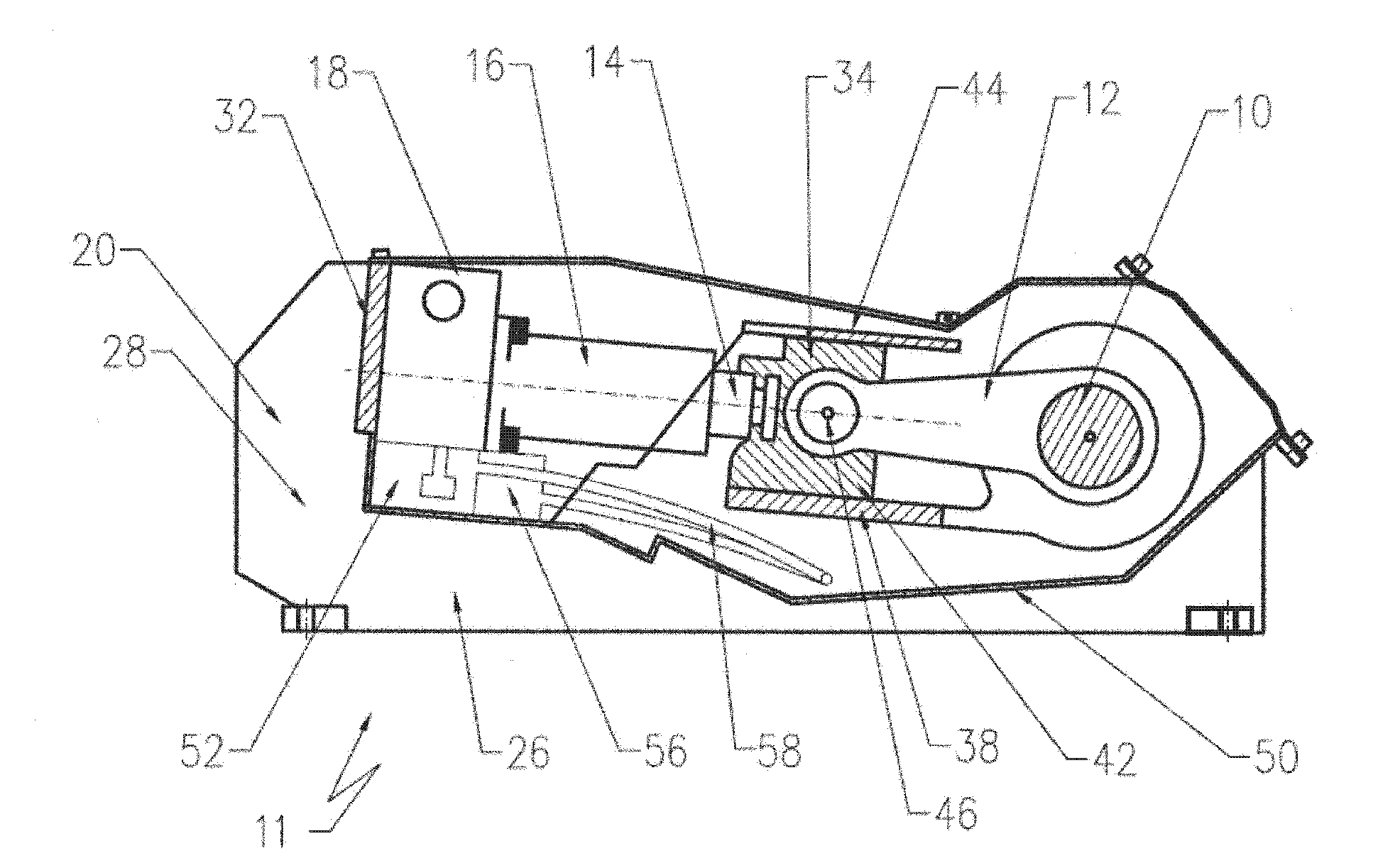
[0044] figure 1 A high-pressure pump is shown very simplified with a housing 11 in which a crankshaft 10 is rotatably mounted and driven by an electric motor (not shown), which can be flange-mounted, for example, on the side of the housing. Crankshaft 10 drives pistons 14 via each connecting rod 12 , a total of three pistons being provided in the exemplary embodiment shown. Each piston 14 is guided in a cylinder 16, which is fixed on the associated cylinder head 18, wherein the piston 14 feeds the fluid from the inlet 54 (see Figure 7 ) is sucked in and discharged at outlet 118 under pressure.

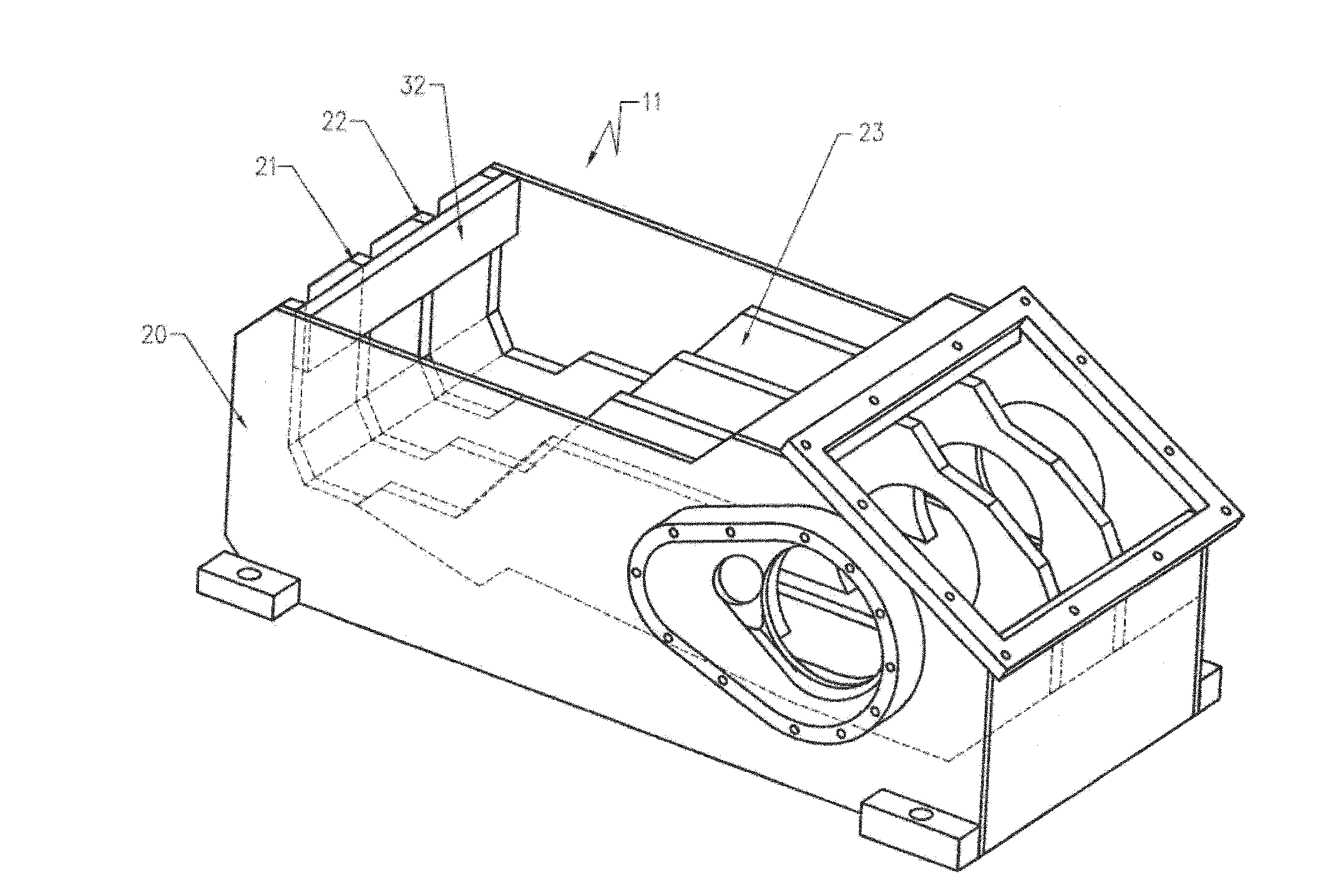
[0045] exist image 3 The housing 11 shown in perspective in the middle has a plurality of flexurally rigid ribs 20 to 23 arranged parallel to one another, which absorb the forces occurring between the crankshaft 10 and the cylinder head 18 .

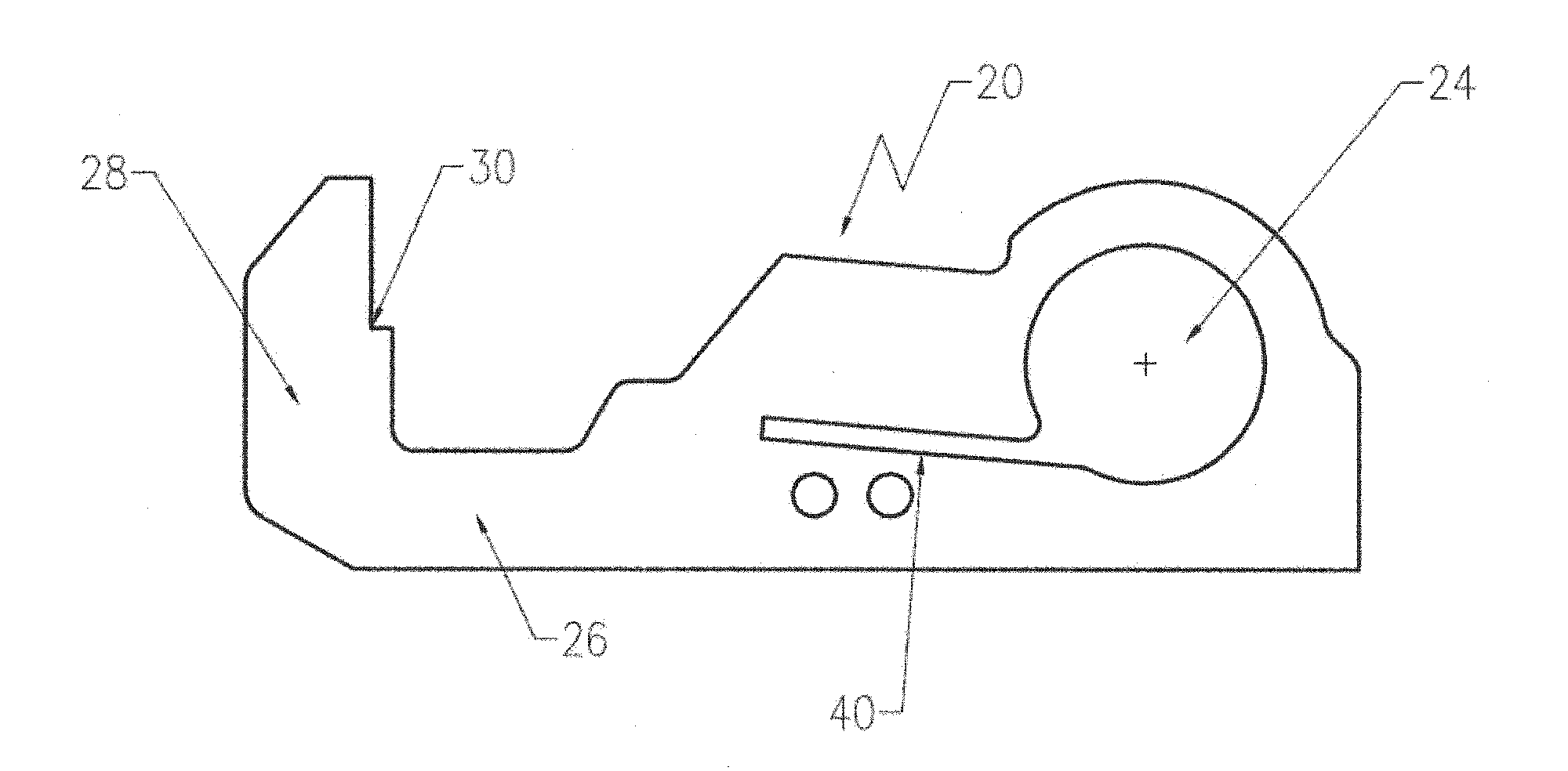
[0046] exist figure 2 The ribs 20 shown in the side view (also ribs 21 to 23 ) are guided around the cylinder head 18 according to the pa...


PUM


Abstract

A high pressure pump has a housing with a crank shaft which drives a plurality of pistons in each case via a connecting rod, with each piston being guided in a cylinder which is secured to a cylinder head and which sucks fluid from an inlet and delivers it under pressure to an outlet.

Description

technical field [0001] The invention relates to a high-pressure pump for downhole production in order to apply a pressure of from about 300 to 350 bar to a water-like fluid. Background technique [0002] Such pumps are basically known and are often designed as piston pumps, in which an electric motor drives a crankshaft via a transmission, on which a plurality of pistons are each arranged via connecting rods. Each piston is arranged in a cylinder and draws fluid from an inlet and expels it under pressure at an outlet. [0003] The construction of the above-mentioned high-pressure pumps for supplying pillars in the mining industry has not been changed or optimized in terms of its construction for a long time. Contents of the invention [0004] The object of the present invention is to provide a high-pressure pump of the above-mentioned type, which is maintenance-free during cost-effective production and has a high efficiency. [0005] This object is achieved by the featur...

Claims


Application Information

Patent Timeline
IPC IPC(8): F04B47/00F04B53/14F04B53/18F04B53/02F04B53/00
CPCF04B53/147F04B53/144F04B53/16
Inventor 马丁·路透
Owner MARCO SYSTEMANALYSE UND ENTWICKLUNG GMBH
Why Eureka
Try Eureka