Articulated robot

a robot and articulation technology, applied in the direction of load-engaging elements, cranes, transportation and packaging, etc., can solve the problems of complex overall control process, inapplicability of conveying frames fixedly installed once, and failure to quickly convey workpieces, etc., to achieve less flexability and high accuracy

Inactive Publication Date: 2008-09-04
HONDA MOTOR CO LTD +1
View PDF8 Cites 21 Cited by
  • Summary
  • Abstract
  • Description
  • Claims
  • Application Information

AI Technical Summary

Benefits of technology

[0012]It is an object of the present invention to provide an articulated robot which is capable of moving a workpiece over a long distance, is less liable to flex under its own weight and the weight of the workpiece carried thereby, and is capable of conveying the workpiece with high accuracy.

Problems solved by technology

Using a carriage, a loader, and an unloader to convey a workpiece, as disclosed Japanese Patent Publication No. 04-009611, fails to convey the workpiece quickly because it is necessary to transfer the workpiece from the loader to the carriage and also from the carriage to the unloader.
As it is also necessary to synchronize the workpiece transfer cycles, the overall control process is complex to perform.
Therefore, the conveying frames that have been fixedly installed once will not be applicable in the case where the layout of the machining units is to be changed.
In addition, since the three apparatus, i.e., the carriage, the loader, and the unloader, are required, they need a large installation space, and the cost of installing them is high.
However, since the disclosed articulated robots also have vertically angularly movable joints, the workpiece carried thereby and the arm move unnecessarily vertically, as with the articulated robot disclosed in Japanese Patent No. 2785597.
If the distances to convey workpieces between the machining units are long, then the arm of the articulated robot needs to be considerably long.
However, the long arm tends to flex unduly due to its own weight and the weight of the workpiece carried thereby, resulting in a reduction in the accuracy with which the arm conveys the workpiece.

Method used


Image

  • Articulated robot
  • Articulated robot
  • Articulated robot

Examples


Embodiment Construction

[0047]An articulated robot according to an embodiment of the present invention will be described in detail below with reference to FIGS. 1 through 12. In the description which follows, a dynamic rotational force produced by rotational movement will be referred to as “inertial moment”, and a static rotational force produced downwardly by gravity or the like will be referred to as “static moment” or simply “moment”, so that these forces will be distinguished from each other.

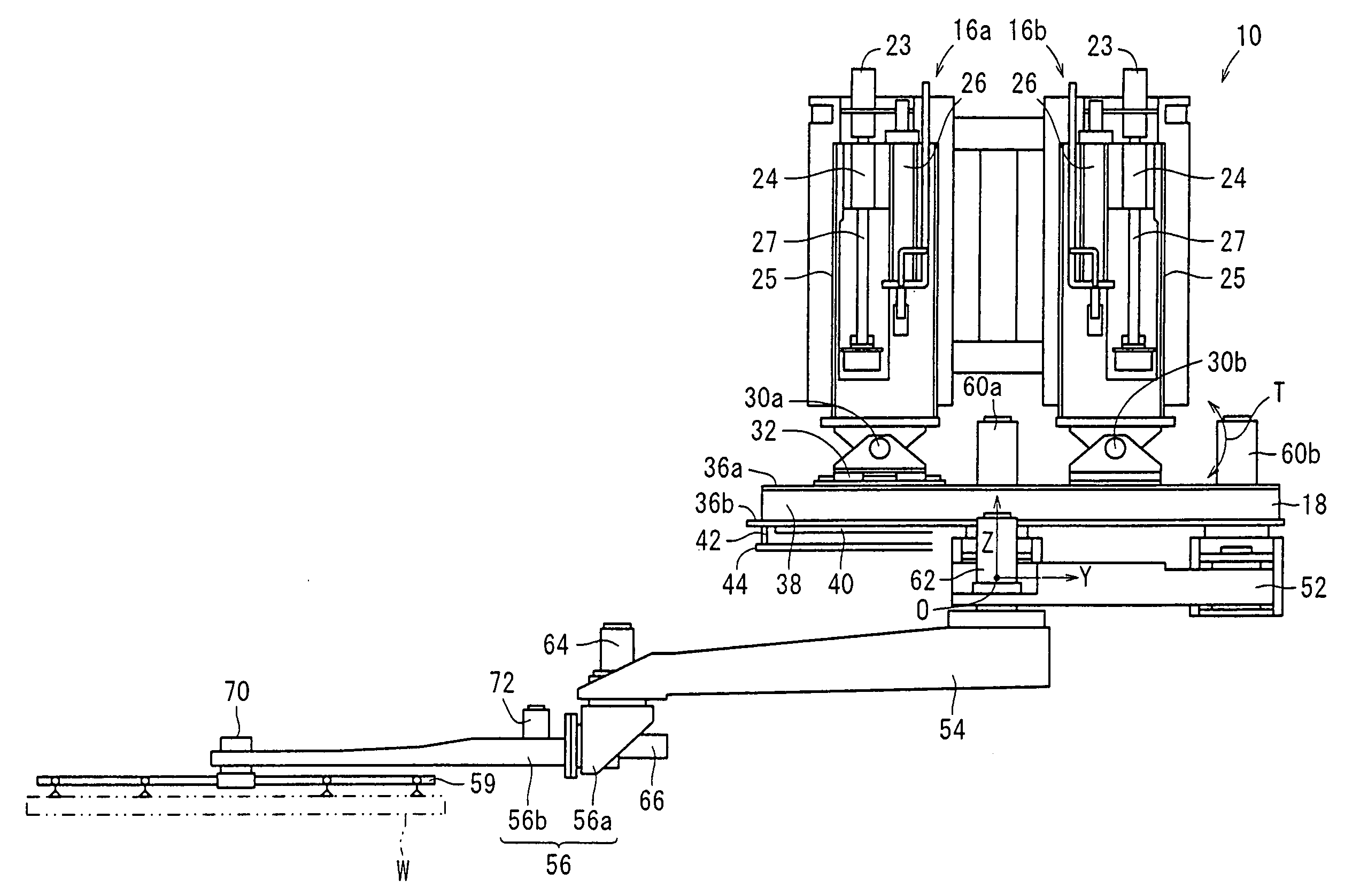
[0048]As shown in FIG. 1, the articulated robot, generally denoted by 10, according to the embodiment of the present invention serves to unload a workpiece W from a machining unit 12 and load the workpiece W into another machining unit 14.

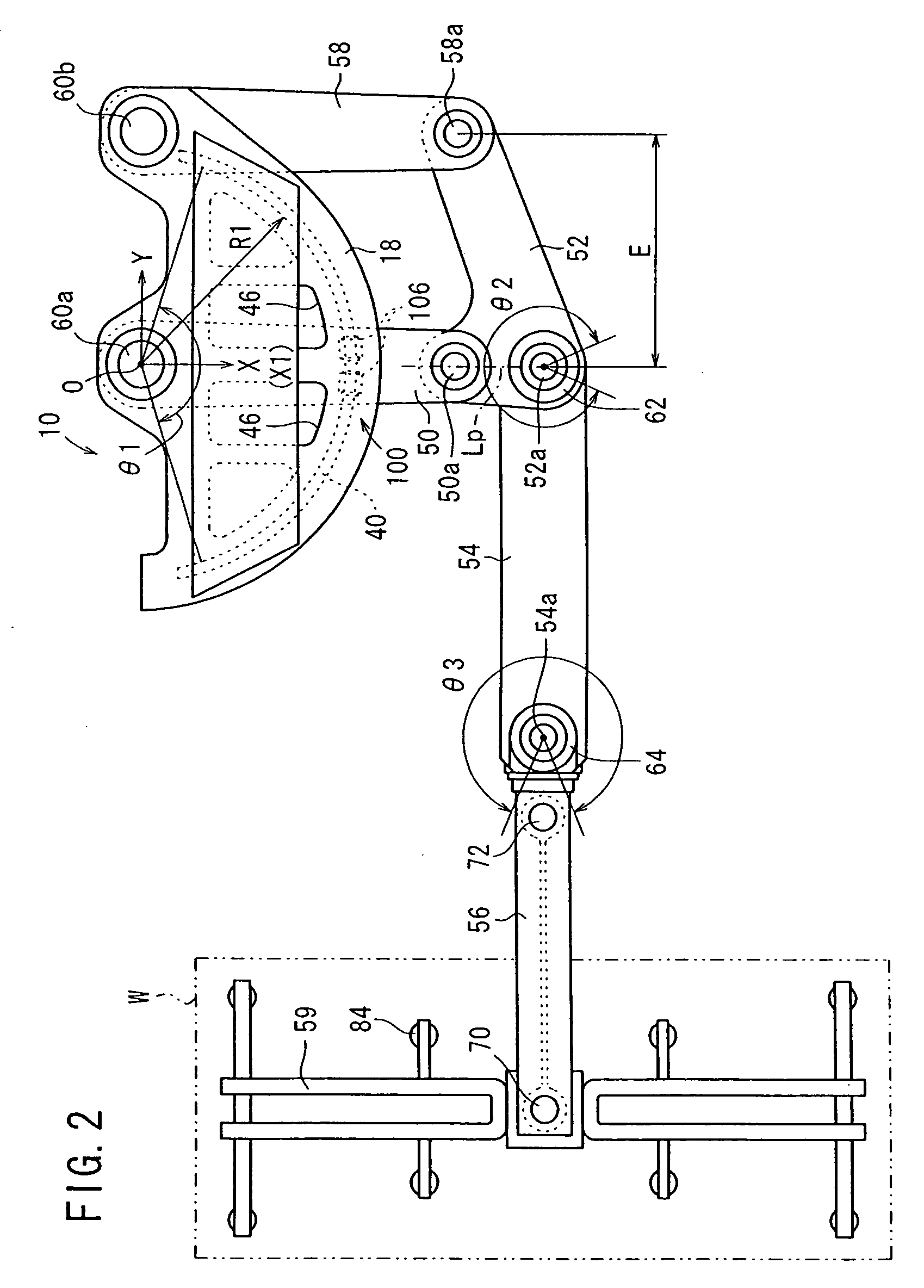
[0049]The articulated robot 10 comprises a pair of parallel lifting and lowering devices 16a, 16b, a support plate (support member) 18 which can be lifted and lowered by the lifting and lowering devices 16a, 16b, an arm assembly 20 connected to the support plate 18, and an end eff...


PUM


Abstract

An articulated robot includes a first arm which is horizontally angularly movable, a sectorial support plate coaxial with a center about which the first arm is angularly movable, an auxiliary arm parallel to the first arm, and a joint member connected to respective distal ends of the first arm and the auxiliary arm. An arcuate rail is mounted on the support plate. The first arm, the auxiliary arm, and the joint member make up a parallel link mechanism. The arcuate rail engages an engaging assembly mounted on an upper surface of the first arm. A second arm is angularly movably connected to the joint member, and a third arm is angularly movably connected to the distal end of the second arm. An end effector for attracting a workpiece is connected to the distal end of the third arm.

Description

BACKGROUND OF THE INVENTION[0001]1. Field of the Invention[0002]The present invention relates to an articulated robot having a plurality of arms connected by angularly movable joints, and more particularly to an articulated robot movable in a wide horizontal range.[0003]2. Description of the Related Art[0004]It is often customary in vehicle manufacturing factories for workpieces to be progressively machined while being conveyed between a plurality of stations or machining units. The workpieces should desirably be conveyed quickly for increased productivity.[0005]Proposed means for conveying workpieces include a reciprocatingly movable carriage for conveying workpieces between machining units, and a loader and an unloader for transferring workpieces between the carriage and the machining units (see, for example, Japanese Patent Publication No. 04-009611). The proposed means are capable of moving workpieces over a long distance.[0006]Processes for conveying workpieces with articulated...

Claims


Application Information

Patent Timeline
Patent Type & Authority Applications(United States)
IPC IPC(8): B66C23/00
CPCY10T74/20329B66C1/0256
Inventor TANAKA, TSUTOMUSUZUKI, MASANAOSUNA, HIRONOBU
Owner HONDA MOTOR CO LTD
Why Eureka
Try Eureka