Dehumidifying method and system

A dehumidifier fan and humidity technology, applied in heating and ventilation control systems, heating and ventilation safety systems, heating methods, etc., can solve the problems of not being able to automatically control the start and stop of dehumidifiers, and being unable to understand the relative humidity of the air environment in the computer room, etc. To achieve the effect of improving service life, improving utilization rate and saving energy

Inactive Publication Date: 2012-03-14
DAWNING INFORMATION IND BEIJING
View PDF7 Cites 28 Cited by
  • Summary
  • Abstract
  • Description
  • Claims
  • Application Information

AI Technical Summary

Problems solved by technology

[0005] Aiming at the defects in the prior art that the dehumidification of the working environment through the above-mentioned technical solutions cannot be performed in a timely and automatic manner to control the start and stop of the dehumidifier, and the specific relative humidity value in the air environment of the computer room cannot be known, the present invention proposes a solution that can solve the above-mentioned defects. Dehumidification method and dehumidification system

Method used


Image

  • Dehumidifying method and system
  • Dehumidifying method and system
  • Dehumidifying method and system

Examples


Embodiment Construction

[0028] The preferred embodiments of the present invention will be described below in conjunction with the accompanying drawings. It should be understood that the preferred embodiments described here are only used to illustrate and explain the present invention, and are not intended to limit the present invention.

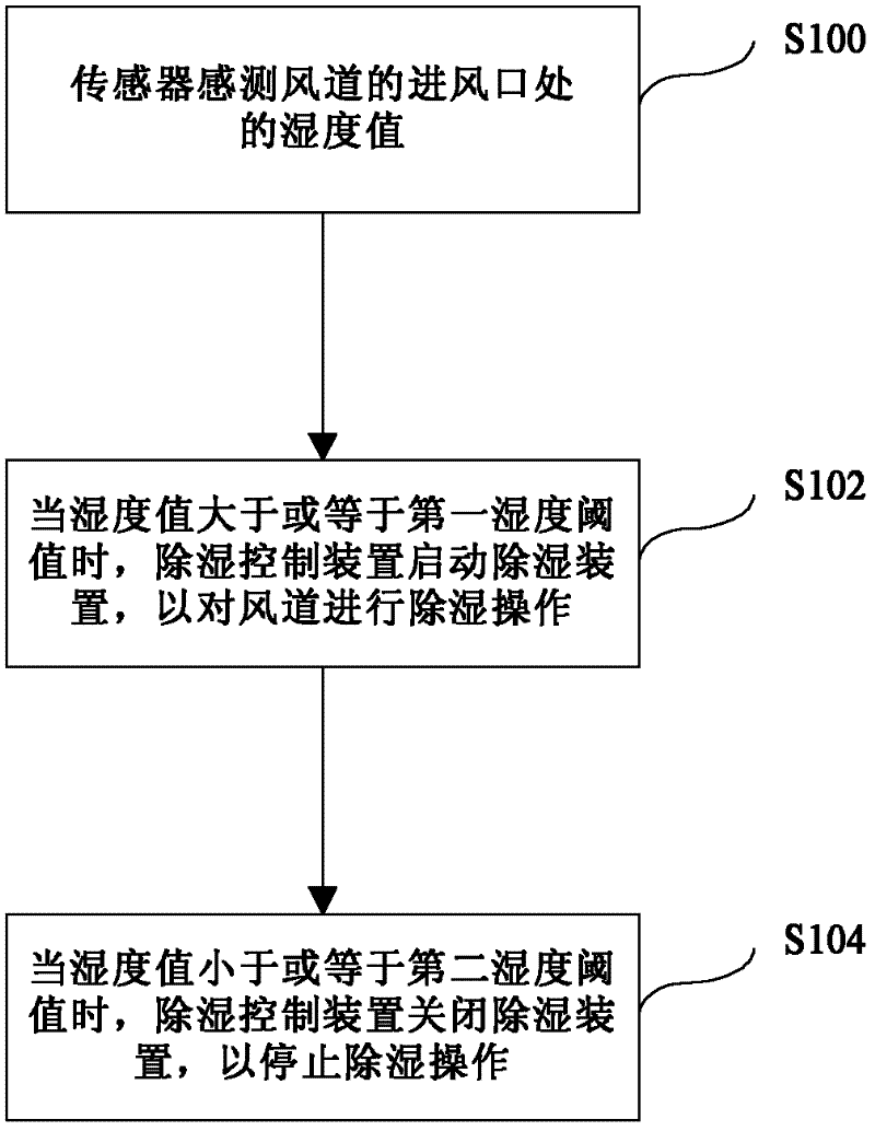
[0029] figure 1 is an overall flowchart of the dehumidification method according to the embodiment of the present invention.

[0030] Step S100: The sensor senses the humidity value at the air inlet of the air duct. The humidity value is the relative humidity value, which is the ratio of the absolute humidity of the humid air to the maximum absolute humidity that may be reached at the same temperature, or the ratio of the partial pressure of water vapor in the humid air to the saturation pressure of water at the same temperature. The sensor is a relative humidity sensor, which is arranged at the air inlet of the air duct, and senses the relative humidity value of t...


PUM


Abstract

The invention provides a dehumidifying method. The dehumidifying method comprises the following steps: a sensor is used for sensing the humidity value of an air inlet of an air flue; when the humidity value is greater than or equal to a first humidity threshold, a dehumidifying control device starts a dehydrating unit for dehumidifying the air flue; and when the humidity value is greater than or equal to a second humidity threshold, and a dehumidifying control device closes the dehydrating unit so as to stop the dehumidifying operation. In the method, through setting the first humidity threshold and the second humidity threshold, the humidity in a machine room air environment is controlled in the range required by a user, the automatic control of effective dehumidification is realized, the service life of a dehumidifying system is prolonged, and the energy consumption is reduced. The invention also discloses the dehumidifying system.

Description

technical field [0001] This invention relates generally to air handling equipment and, more particularly, to methods and apparatus for dehumidification. Background technique [0002] If the air humidity is too high, the contact resistance of the plug-in at the joint of the component will increase, causing it to operate incorrectly, and the components that are not well sealed may be broken down. Rapid changes in relative humidity will shorten the life of components such as transistors. If the humidity control is not good, it will cause condensation on the wall of the computer room and the inside of the program-controlled machine, which will easily cause corrosion and mildew, and cause the circuit components of the program-controlled machine to short-circuit, causing failures and accidents. For computer rooms that require relatively high air relative humidity, it is necessary to be equipped with a dehumidification device. [0003] A dehumidifier with adjustable dehumidificat...

Claims


Application Information

Patent Timeline
Patent Type & Authority Applications(China)
IPC IPC(8): F24F11/00
Inventor 沈卫东刘金星李宁童中原
Owner DAWNING INFORMATION IND BEIJING
Why Eureka
Try Eureka