Induction blow-out vent

A technology of air outlet and ejection outlet, which is applied in the field of inductive air outlet to achieve the effects of easy manufacture, low static pressure, and elimination of uneven temperature

Active Publication Date: 2012-03-14
KIMURA KOHKI CO LTD
View PDF7 Cites 12 Cited by
  • Summary
  • Abstract
  • Description
  • Claims
  • Application Information

AI Technical Summary

Problems solved by technology

Therefore, it is necessary to insulate the entire outlet

Method used


Image

  • Induction blow-out vent
  • Induction blow-out vent
  • Induction blow-out vent

Examples


Embodiment Construction

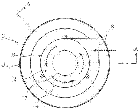
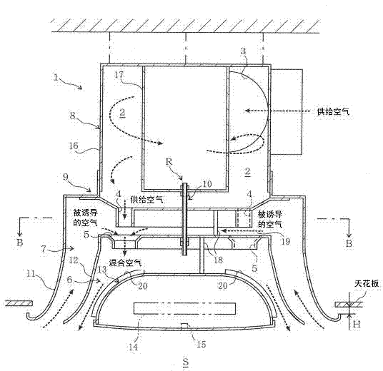
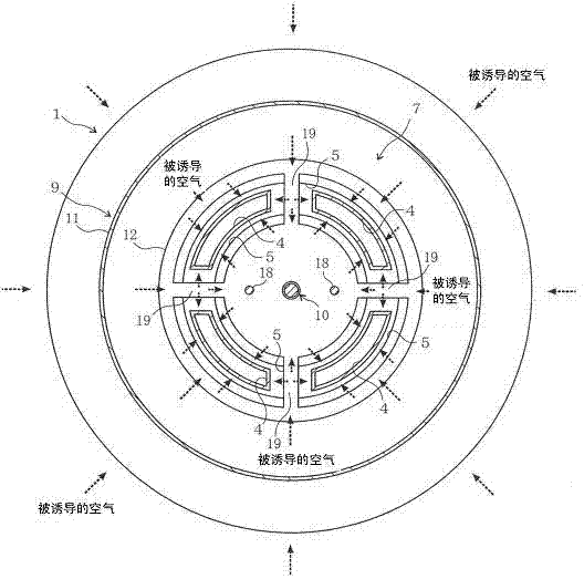
[0044] Figure 1 to Figure 5 An example of the induction air outlet of the present invention is shown. The induction air outlet is provided with a main body 1 that induces the air in the air-conditioned space S to be mixed with the supply air sent in from the outside, and blows the mixed air to the air-conditioned space S. . The main body 1 is composed of a supply air introduction part 8 having a partition part 2 , and an outlet part 9 having an air outlet 4 , an induction port 5 , a mixed air outlet duct 6 , and an induction duct 7 . The air-conditioned space S is a space such as a room or a hall of various buildings such as an office building, a hospital, and a restaurant. An induction air outlet is provided on the ceiling or the like of the air-conditioned space S. As shown in FIG. Air-conditioning air and the like are supplied to the induction outlet through ducts and the like from an air conditioner (not shown). In addition, the dashed-line thick arrows in each drawing...


PUM


Abstract

The present invention provides an induction blow-out vent which is provided with a main body, an annular separation part is formed inside the main body, and an air supply outlet is arranged, thus supplying air can be delivered toward the circumference of the separation part. On the downwind of the separation part, a plurality of air injection vents for injecting the supplying air are arranged along the circumference of the separation part, and each air injection vent is arranged on the downwind induction vent of the air injection vents, thus through blowing in the supplying air injected by the air injection vents, the air of air-conditioned space can be induced. A guided passage is also arranged, a mixing air blow-out wind channel for guiding the mixing air of the supplying air and the induced air into the air-conditioned space is formed on the downwind of the induction vents, and the induction blow-out vent is also provided with an induction wind channel for guiding the induced air from the air-conditioned space into the induction vent. Moreover, the induction blow-out vent is good in diffusivity and small in heat insulation treatment scope.

Description

technical field [0001] The present invention relates to an induction outlet. Background technique [0002] There are low-temperature blowing air conditioning systems that supply air from an air conditioner at a lower temperature than normal and have a smaller air volume, and supply air from an outlet installed in a room to be conditioned, for the purpose of reducing blowing power. If such a general dual-flow outlet is used in such an air-conditioning system, since the supply air temperature is low and the air volume is small, the air flow does not diffuse, and cold draft and condensation occur. [0003] Patent Document 1: Japanese Patent Application Laid-Open No. 7-41345. Contents of the invention [0004] In order to prevent such a situation, an air outlet as in Patent Document 1 has been proposed. In order to prevent the decrease of diffusibility, a rotating paddle is installed at the outlet, but there are problems in that the structure is complicated, the pressure los...

Claims


Application Information

Patent Timeline
Patent Type & Authority Applications(China)
IPC IPC(8): F24F13/06F24F13/22F24F13/24
Inventor 木村惠一浦野胜博土井健司
Owner KIMURA KOHKI CO LTD
Why Eureka
Try Eureka